
A device called a Selsyn was developed about 1925. This comprised of a system whereby a generator and a motor so connected by wire that angular rotation or position in the generator is reproduced simultaneously in the motor.
The generator and receiver are also called, a transmitter and receiver.
About 1942 or 43 the term, synchro, became the general term, replacing the word, selsyn. This comprised of a system whereby a generator and a motor so connected by wire that angular rotation or position in the generator is reproduced simultaneously in the motor. The generator and receiver are also called a transmitter and receiver.
Synchros are special a-c motors employed for transmitting angular position and rotation over a distance to far for mechanical shafting to do the job. Of course in the USN synchros are usually thought of as the devices that transmit information about gun fire control systems, in the civilian world they do a host of other things.
1. Remote indication of position, Such as indicating the position of generator rheostats, water-wheel governors, water-reservoir levels gates or valves, and turntables.
2. Remote signaling systems, such as signaling from switchboard to generator room, steel-mill furnace to blower room, and marine signals between engine room and bridge.
3. Automatic or remote position control, such as system frequency, synchronizing of incoming generators, water-wheel governors, gates or valves, color screens on lights in theaters, and motor drives.
4. Operation of two machines so as to maintain a definite time-position relation or a definite speed relation, such as lift bridges, hoists, kiln drives, elevators, unit printing presses, and conveyors.
Synchros are known by various trade names such as Selsyn, Synchrotie, Autosyn, and Telegon. Units are available in single-phase and three-phase types. The poly-phase units conform in appearance and general characteristics to a three-phase wound-rotor induction motor. The single-phase units have a three-phase wound secondary and a single-phase primary. Some single-phase units are constructed with the primary located on the stationary member of the machine and others with the primary on the movable member. Depending upon the torque developed by the machine, synchros are classified as indicating synchros or power synchros.
Power synchros are always of three-phase construction. Most of the indicating synchros are constructed single-phase. The indicating synchros are manufactured in a general-purpose type and a high-accuracy type. The general-purpose type will indicate angular position within an accuracy of plus or minus 5 deg, and the high-accuracy type provides an accuracy of indication within plus or minus 1 degree.
A synchro system requires the use of at least two synchro machines. The connections for two single-phase units are, shown in Fig. 1 and those for two three-phase units in Fig. 2. With both the single-phase and the poly-phase units, if the rotors of the two machines are in corresponding positions, the voltages of the two secondaries at each instant of time will be equal in magnitude and opposite in direction. Therefore, no current will flow in the rotor circuits, no torque will be developed in either machine, and the machines will be in equilibrium. When the two rotors are not in corresponding positions, the voltages of the two secondaries will not neutralize each other and a current will be produced in the two secondaries. This current will produce torque in the machines, which will act upon the rotors, tending to move them into corresponding positions.
In signaling or indicating applications, the synchro located at the sending end is called the transmitter and the synchro at the receiving end is called the receiver. If desired, a number of receivers can be connected in parallel to a single transmitter. The torque excited upon each receiver will be reduced from that available when only one receiver is used. The torque can be calculated from the following formula:
Tr = T1 x 2 divided by (N + 1)
Where Tr, is the torque available at each receiver, T1, is the torque available if only one receiver is used, and N is the number of receivers.
When it is desired to have the position taken by the receiver differ from that of the transmitter, a three-phase synchro is introduced between the transmitter and the receiver. This intermediate synchro is called a differential synchro. With such a system, the receiver will take up a position that will be either the sum or the difference of the angles applied to the transmitter and the differential. Conversely, if two synchros are connected through a differential synchro and each is turned through an angle, the differential synchro will indicate the difference between the two angles, shown in Figure 4.
The fundamental synchro circuit generally used for control purposes is shown in Fig.3. When the positions of the rotors coincide, a maximum voltage will be induced in stator No. 2. When the rotors are, displaced 90 electrical degrees from each other, no resultant voltage will be produced between the terminals of rotor No. 2. This is true, since the axis of the winding rotor No 2 will be located 90 electrical degrees from the axis of the, field produced in machine 2. The system is adjusted so that, when the desired condition exists, the rotors will be 90 electrical degrees displaced from each other. This is the equilibrium position. The circuit therefore functions to produce an error or voltage in the stator of machine 2 whenever there is a displacement of the shafts from the equilibrium position. The relative polarity of the error voltage depends upon the direction of the displacement. The error voltage can be employed to instigate the functioning of other devices, which will operate to correct the condition causing the displacement. These correction devices will function until the synchros are brought into the equilibrium position, when absence of voltage in rotor No. 2 will stop their functioning.
In the military all windings of the rotors and stators are connected and terminated as “Like Wound” devices. “Like Wound” means that the numbered wire ends are terminated and numbered from the windings so that the coils in all machines are in identical positions. This is done so that if replacement is necessary there is no need to worry about the wiring being connected wrong or backwards.
The waveform produced by the new machine will be in or of the same polarity and phase angle as the machine being replaced. Only mechanical re-alignment of the machine is necessary.
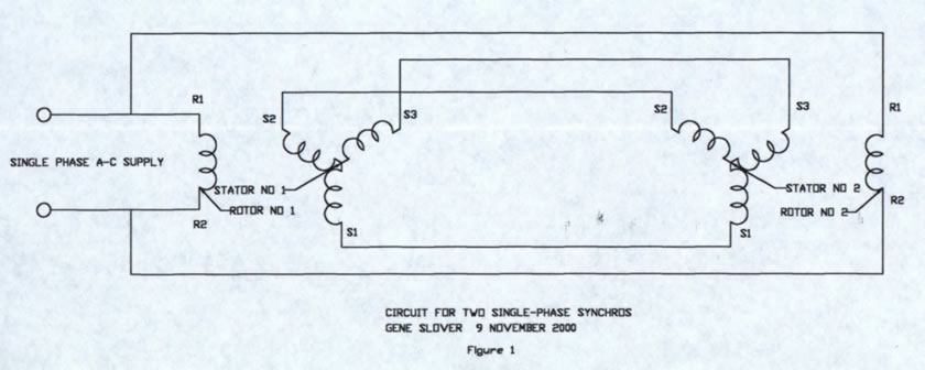
FIG. 1 Circuit for two single-phase synchros.
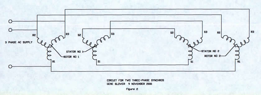
FIG. 2 Circuit for two three-phase synchros.FIG.
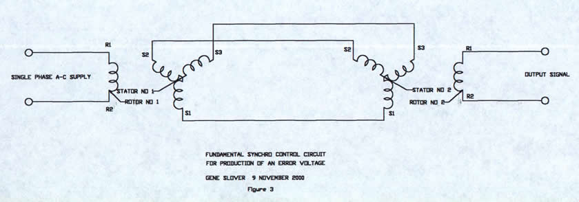
3 Fundamental synchro control circuit.
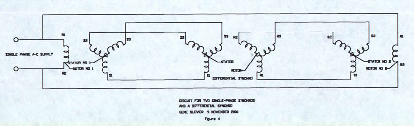
FIG. 4 Circuit for two single-phase synchros and a differential synchro.
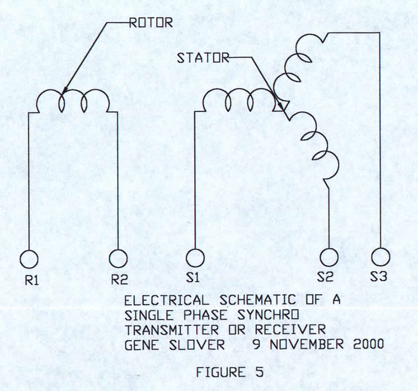
FIG. 5 Schematic of a single-phase transmitter or receiver synchro.
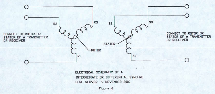
FIG. 6 Schematic of a three-phase transmitter or receiver or a differential synchro.
Related Pages:
Ordnance Pamphlet 1303 US Navy Synchros
Find our other Ordnance Pamphlets using Menu at botom of page
Click Misc., then Ordnance Pamphlets


