| NAVAL ORDNANCE AND GUNNERY CHAPTER 12 TORPEDOES |
| J. Above-Water Torpedo Tubes 12J1. Function Torpedo tubes serve the following purposes: 1. House and protect the torpedo (including heating in cold weather) until the instant of firing. 2. Provide means for setting torpedo gyro angle, running depth, and, where required, torpedo speed as necessary, up to the instant of firing. 3. Expel the torpedo with sufficient force to clear the firing ship and with such velocity and direction that it will remain on its firing course until its engine develops enough power for self-propulsion. 4. As expulsion starts, trigger the torpedo so as to start its engine and gyro. These functions apply to submarine tubes as well as above-water tubes. Since, however, the former must also serve as pressure members of the ship’s hull, they incorporate additional features which are not suitable for discussion in this textbook. 12J2. Type and location Above-water tubes may be classed as trainable or fixed. Until after World War II, United States Navy destroyers and destroyer escorts armed with torpedoes all carried trainable tubes. Destroyers mount either the Mark 14 or the Mark 15 quintuple tubes. The two types are substantially identical, except that the latter was designed to accommodate a blast shield for the protection of personnel from the blast of adjacent guns. Trainable tubes require large clear deck areas, and in all ships retaining torpedoes they are mounted topside on the ship’s centerline as shown in figure 1B2. From this location torpedoes can be fired through limited arcs of train on either side of the ship. In the latter phases of World War II the necessity for increasing antiaircraft armament put a high premium on topside deck space. New destroyer and escort designs have therefore featured above-water torpedo tubes in locations other than weather deck. Such tubes are housed and fixed (i. e., nontrainable). With fixed tubes greater gyro angles must be used in firing than from trainable tubes; and, since torpedoes tend to depart more widely from their predicted courses when fired with large than with small gyro angles, this is a disadvantage. Also, tubes must be carried on both sides of the ship. However, the weight gained by eliminating the training gear, pivots, etc., provides a partial compensation. The interior location permits all tubes to be located in the same compartment of the ship, in which reload torpedoes and quick-reloading gear may also be carried. Fixed tube designs include the Marks 23 and 24. 12J3. 21-inch Above-Water Torpedo Tube Mark 14 Each Mark 14 torpedo tube consists of five barrels, supported in a single saddle which functions like the carriage of a gun except that no provision is made for elevating the barrels. The saddle rests on a roller bearing assembly supported by a stand. The stand, like that of a gun, contains a training circle. The tube is normally trained by an electric-hydraulic drive, similar to a gun mount train drive and controlled by the operation of the training handwheels on top of the mount. Provision is made for manual train in case of power-drive failure. See figure 12J1. |
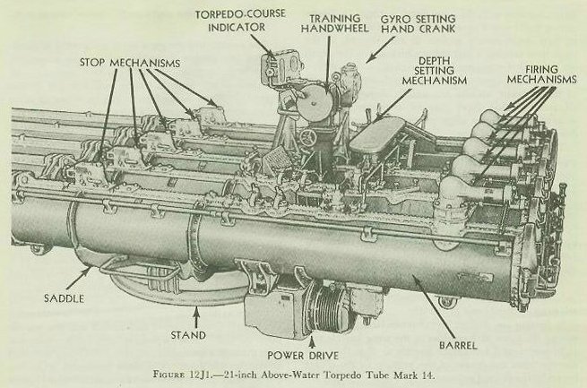 |
| Each barrel is an assembly of a main barrel, a spoon, and a spoon extension. The main barrel is cylindrical in shape, but the spoon and spoon extension are open on the under side. The spoon extension is hinged at the top, so that it can be folded back along the spoon to save deck space. Within the barrel, at the bottom, are rollers which facilitate loading the torpedo. Running the length of the top of the barrel to the end of the spoon extension is a T-shaped guide slot. The guide stud on the torpedo rides in this slot as the torpedo is fired. The stud prevents the torpedo from dropping downward before the tail has cleared the main barrel, thereby preventing damage to the tail assembly and helping to keep the torpedo horizontal as it is launched. The breech end of the barrel is closed by a door, so flanged and sealed that it will hold the pressure developed by the impulse charge in launching the torpedo. Torpedoes are expelled from each barrel individually by an impulse charge fired in the firing mechanism on top of the barrel. A passage from the firing mechanism leads to the space between the door and the torpedo. Normally, charges are fired electrically from the bridge, but they can be fired by percussion at the tube if necessary. Each black-powder impulse charge is contained in a special 3-inch case about 13 inches long. A torpedo stop is employed to keep the torpedo from sliding in the barrel. The stop is bolted to the T-guide of each barrel. It incorporates a back and a front stop, between which the torpedo’s guide stud is gripped. After the torpedo is loaded, a tension link is placed in the housing to hold the front stop in position. When the torpedo is fired, the tension link parts and the front stop swings out of the way of the guide stud. Also mounted on the T-guide of each barrel is the tripping latch. It projects into the barrel and engages and trips the starting lever of the torpedo as it begins to move forward in the barrel. As stated in article 12C10 this is essential in order to start the torpedo power plant. Atop the barrels are a seat for the trainer and gyro setter, the train controls, and the sight and fire control apparatus. Also on top of the barrels, and thus within easy reach of the crew, are the gyro-setting, depth-setting and speed-setting mechanisms. The barrels also have covered openings which permit access to the torpedoes for fueling, air charging, and other maintenance routine. 12J4. Torpedo-setting mechanism The depth-setting mechanisms, located on top of the barrels, are arranged to set the five torpedoes simultaneously with the same depth setting. A depth-setting hand crank operates through gears and shafts to turn depth-setting sockets in each barrel, at the same time turning a dial index which shows the depth set. A socket-engaging lever moves the socket of each barrel into engagement with the depth-setting spindle of the torpedo; sockets are usually engaged well in advance, so that there may be assurance that the sockets and spindles align properly. They must be disengaged before firing. The speed-setting mechanisms of the barrels are separate. Each consists of a permanently mounted wrench protruding upward from a cylindrical housing within which is a spring that holds the spindle up out of engagement with the torpedo’s speed-setting socket except when the wrench handle is pushed down by hand, and a cam that allows the wrench to spring up only when properly positioned at the HIGH, INTERMEDIATE, or LOW speed position. The wrench and spindle must never be left in the down position. The gyro-setting mechanism provides a means for: 1. Setting the gyros of the torpedoes in all five barrels to any desired basic gyro angle. 2. Setting any desired spread up to 10 degrees; i. e., setting the gyros of torpedoes in the wing barrels and right-center and left-center barrels so that they will diverge from the course of the torpedo in the center barrel by the desired amount. 3. Engaging the gyro-setting spindles in the sockets of the torpedoes, and withdrawing them, at will. Two separate handcranks are used, one for setting the basic gyro angle and the other for making spread-angle setting. They work together through a differential at each tube to set the proper resultant angle on each torpedo. The angles set are shown on the dials of the gyro-setting mechanism; basic gyro angle shows also on the dials of the torpedo course indicator, which is described in volume II. Spindles must be disengaged before the torpedoes are fired. 12J5. Torpedo tube sight and torpedo course indicator The trainer and the gyro setter are guided in determining the proper firing course for the torpedoes, either by the torpedo tube sight (in local control) or by the dials of the torpedo course indicator (in remote control). Since an understanding of either of these instruments presupposes a comprehension of the torpedo fire control problem, they are discussed in volume II. |
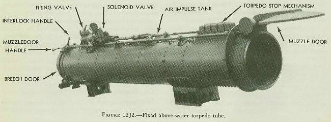 |
| 12J6. 21-inch above-water torpedo tubes Marks 23 and 24 Figure 12J2 represents a single-barrel fixed-type nontrainable torpedo tube designed to mount singly or in groups of two or more on each side of a vessel. The tubes are mounted athwartship within the superstructure, with muzzles extending through the sides of the deck house. The tubes are constructed of a light-weight aluminum alloy. They are air-fired and are suitable for launching only torpedoes having electrically set torpedo controls. The breech and muzzle doors arc so interlocked that firing can occur only when the breech door is closed and locked and the muzzle door opened. The torpedo control cable enters the tube through a special electrical terminal plug mounted in the breech door. The door connector is in two parts. One part is permanently installed in the center of the door, while the inner half is affixed to the torpedo cable. The two halves are coupled together after the torpedo is loaded into the tube. The cable is cut by the forward motion of the torpedo at launching. Torpedo Tube Mark 23 is designed to launch 21-inch torpedoes with a length not exceeding 161 inches. Torpedo Tube Mark 24 is designed to launch 21-inch torpedoes with a length not exceeding 246 inches. Both tubes are supplied with adapter rings which can be installed so as to permit launching a 19-inch diameter torpedo. |