| NAVAL ORDNANCE AND GUNNERY CHAPTER 12 TORPEDOES |
| G. Tail Section of a Mark 15 Torpedo 12G1. General The tail section is a short, truncated cone. Holes are drilled in its forward end so that it may be secured to the afterbody with joint screws. The principal parts that it carries are: 1. The surfaces that drive the torpedo through the water-the two propellers. 2. The surfaces that control the path of the torpedo-the tail blades and rudders. 3. The sleeves and hubs that support the propellers. 4. The rods and yokes that operate the rudders. |
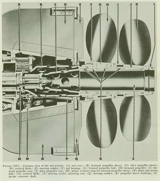 |
| 12G2. Construction Figure 12G1 is a cutaway view of the tail section. A bearing in the after bulkhead of the afterbody supports the after end of the forward propeller shaft. The after propeller shaft turns, in a bronze bushing, inside the forward propeller shaft. The forward propeller sleeve (B in figure 12G1) is keyed to the forward propeller shaft and secured to it by screws. The after propeller sleeve (C) is secured to the after propeller shaft in the same way. The forward propeller sleeve turns in the tail bearing (F). The after propeller sleeve turns in four bronze bushings (R) inside the forward sleeve. The grease reservoir shell (S) holds a supply of grease inside the after propeller sleeve. When the torpedo is under way, the hot exhaust gases melt the grease in the reservoir. Centrifugal force pushes the melted grease through small passages in the propeller sleeves, to lubricate the bushings (R) and the tail bearing (F). The forward propeller hub (G) is keyed to the forward propeller sleeve. The forward propeller nut screws onto the sleeve to hold the propeller in place. Locking screws keep the nut from working loose. Half of each locking screw is in the nut, and half in the propeller. The after propeller hub (J) is an integral part of the after propeller sleeve. Except for that, the mounting of the after propeller is the same as that of the forward propeller. Each of the 2 propellers has 4 blades. The exhaust gases pass through openings in the after bulkhead of the afterbody, and enter the tail through exhaust valves. (One of these valves is visible in figure 12G1.) Springs in the exhaust valves hold them shut, except when the pressure of exhaust gases forces them open. The exhaust valves thus keep water out of the afterbody at the end of an exercise run, and when the torpedo is in the flooded tube of a submarine. When the torpedo starts, pressure builds up in the exhaust tubes and pushes the valves open. The exhaust gases then flow into the tail, into the propeller sleeves through the holes in their forward ends, and out to the sea. The four tail blades are riveted to projections on the outside of the tail cone. They stabilize the torpedo as it travels through the water. The two pairs of rudders are mounted at the after edges of the tail blades. Each rudder turns in an inner bearing on the tail cone, and an outer bearing screwed to the tail blade. These outer bearings have a double purpose. Their outer edges serve as bearing surfaces to guide the tail as the torpedo slides through the torpedo tube. |