| NAVAL ORDNANCE AND GUNNERY CHAPTER 12 TORPEDOES |
| H. Aircraft Torpedoes 12H1. Construction and use Aircraft torpedoes came into common tactical use during World War II, as alternate weapons to aircraft bombs for use in attacks on surface ships. Torpedo attacks, however, ordinarily are not made against well-defended units, unless supporting attack is made simultaneously by other types of planes to divide the enemy antiaircraft fire. When properly employed, torpedo attack may force enemy ships to maneuver into an unfavorable position with respect to a main attack delivered by own ships, or accept the penalty of torpedo hits. Aircraft torpedoes must be able to withstand heavy water impacts. They must also be capable of maintaining stable flight from plane to water, and a stable course through the water to the target. The Mark 13 torpedo, shown in figure 12H1, is one of the older types still in service use. It is similar to the Mark 15 torpedo but differs in certain details of size and design, including the incorporation of special stabilization elements necessary for effective launching from aircraft. An aircraft torpedo usually is suspended between two racks, which have suspension cables running between them and around the torpedo. A small stop bolt, projecting downward from the plane into a hole in the torpedo casing, serves to prevent fore-and-aft slipping of the torpedo in its cables. When one end of each cable is released, the torpedo falls away. |
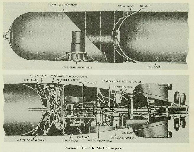 |
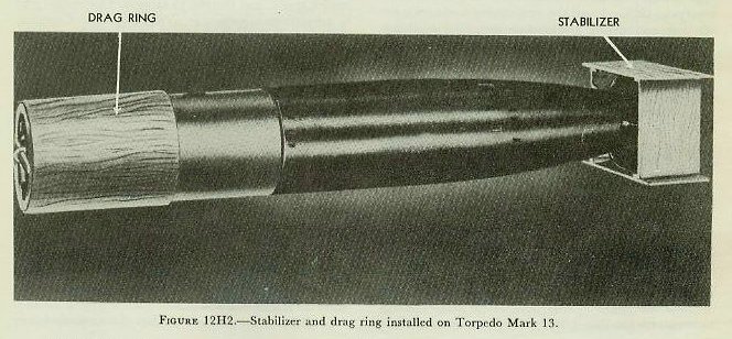
| 12H2. Mark l3 torpedo The Mark 13 torpedo differs from the Mark 15 torpedo in the following ways: 1. The Mark 13 torpedo has better provision for air stabilization, being much shorter and slightly larger in diameter. It is 13 feet 5 inches long, and 22.42 inches in diameter. 2. The Mark 13 torpedo has greater capacity for withstanding water impact. 3. The Mark 13 torpedo contains a smaller explosive charge: 600 pounds of HBX. 4. The Mark 13 torpedo has a shorter designed range: 5,700 yards. 5. The Mark 13 torpedo has a single speed: 33.5 knots. 6. The Mark 13 torpedo has a water trip delay valve to prevent ignition until the torpedo enters the water. 7. The Mark 13 torpedo has a shroud ring around its tail vanes, which tends to minimize hooking and broaching upon water entry, and makes for greater stability during the water run. 8. The Mark 13 torpedo is rigged for launching with a box-shaped plywood stabilizer fitted over the fins and shroud ring. This stabilizer causes the torpedo to fall in a smooth curve, and to enter the water head first. The stabilizer breaks up on impact with the water. A parachute drogue stabilizer has been designed as a substitute for the box stabilizer. 9. The Mark 13 torpedo has a drag ring, in the form of a plywood tube open at each end, fitted over its head. The drag ring slows the torpedo’s rate of fall, tends to reduce wobbling, and acts as a shock absorber on water impact. The stabilizer and drag ring are shown in figure 12H2. This drag ring is not used when the torpedo is rigged with a parachute stabilizer. Near the after end of the torpedo is a starting lever. When the torpedo is installed on the plane, a toggle is hooked to this lever and is attached to the aircraft by a lanyard. When the torpedo is released, action of the lanyard and toggle trips the starting lever, but a water trip delay valve serves to prevent the combustion flask from lighting off until water entry. A gyro-locking mechanism is also provided. When the torpedo is installed on the plane, the gyro is locked with its axis parallel to the axis of the plane. The gyro begins to spin on release from the plane. The gyro will therefore keep the torpedo on the course determined by the direction of aircraft travel at the instant of release. |
 |
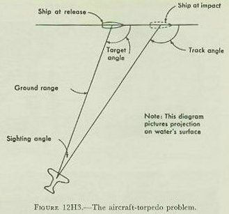
| 12H3. The aircraft-torpedo problem The basic problem in launching a torpedo from an aircraft is to put the torpedo in the water on a collision course with the target. Although improvements in aircraft torpedoes have made launchings possible from greater altitudes and at longer ranges, speed and mobility of attacking planes simplify the problem to the extent that experienced pilots can obtain satisfactory accuracy without the use of special computing gear. The pilot must be able to (1) estimate target angle (see figure 12H3), (2) estimate target speed, (3) estimate and utilize proper lead, and (4) release the torpedo at the sighting angle which will produce a collision course. Speed of the plane at the point of release usually is established by doctrine, to ensure that the torpedo will enter the water at an angle between 20 and 33 degrees, and not deep-dive or ricochet. When the plane has a speed in excess of 150 knots, and the water is at least 150 feet deep, an entrance angle of 26 to 30 degrees is preferable. The torpedo will assume its preset run-fling depth (up to 50 feet) after water travel of 300 yards; the exploder mechanism is armed after water run of 200 yards. In recent years lightweight directors have been developed for aircraft installation; their use greatly simplifies practical solution of the torpedo problem. |
 |