| NAVAL ORDNANCE AND GUNNERY CHAPTER 12 TORPEDOES |
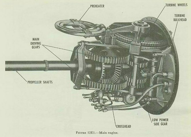
| E. Main Engine of a Mark 15 Torpedo 12E1. General The main engine is located entirely within the afterbody, and is supported by A-frames secured to the after side of the turbine bulkhead. It consists of the turbine wheels, gear reduction train, and propeller shafts, along with the frames, spindles, shafts, and bearings that support these parts, and the oiling system that lubricates them. The main engine of a Mark 15 torpedo, viewed from the starboard side, is shown in figure 12E1. |
 |
| 12E2. Functional description The main engine converts turbine-wheel rotation into propeller rotation. In order to do this effectively, it must have several special features. Because of the high velocity at which the combustion gases strike the turbines, the turbine wheels must turn at high speed in order to use the available energy efficiently. But, if the propellers are to operate efficiently, they must turn more slowly than the turbine wheels, and develop a higher torque. The main engine must therefore include a gear reduction train. The torpedo is provided with two propellers, which rotate in opposite directions but at the same speed. This feature is necessary because the torque developed by a single propeller would tend to roll the torpedo in the opposite direction. As previously stated, the two turbine wheels also turn in opposite directions. But it is not possible to drive each propeller with a different turbine wheel, because the first turbine wheel develops a much higher torque than the second. The main engine must therefore combine the two unequal torques developed by the turbine wheels, and then divide this force equally between the two counter-rotating propellers. Finally, the main engine must continuously lubricate its moving parts throughout the torpedo run. |
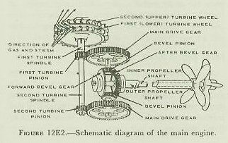 |
| 12E3. Gear train Figure 12E2 is a schematic diagram of the main engine. This illustration should be compared with figure 12E1, bearing in mind that the two views are from opposite sides. (The side gears are not shown in figure 12E2; they will be described later.) Each of the two turbine wheels is mounted on a separate spindle. The first turbine spindle is short and hollow, and carries the first turbine pinion at its lower end. The second turbine spindle is longer, and passes through the opening in the first spindle. The second turbine pinion is mounted at the bottom of the second turbine spindle. |
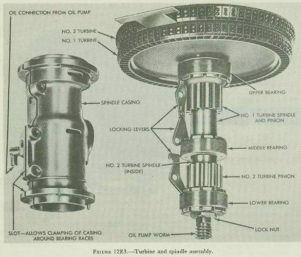
| As they pass through the nozzles, the hot combustion gases expand and reach a high speed-about 4,000 feet per second. They strike the blades of the first (lower) turbine wheel, and spin it counterclockwise (as viewed from the top of the torpedo). The first turbine turns its spindle, and the first turbine pinion, counterclockwise. The pinion meshes with the upper main drive gear, and turns it clockwise. The drive gear turns the upper bevel pinion clockwise. The combustion gases are deflected from the blades of the first turbine, and strike the blades of the second (upper) turbine. The second turbine spins clockwise (still looking down from the top). The second turbine turns the second turbine spindle, and the second turbine pinion. The second turbine pinion turns the lower main drive gear counterclockwise. Each of the 2 bevel pinions meshes with both bevel gears. Working together, the 2 pinions turn the 2 bevel gears. The forward bevel gear turns counterclockwise (looking aft from the forward end of the engine). The after bevel gear turns the forward (outer) propeller shaft, which turns the forward propeller. The forward propeller shaft is hollow; the after propeller shaft turns inside it. The forward bevel gear turns the after (inner) propeller shaft, which turns the after propeller. Because the two propeller shafts are linked together through the bevel gears and bevel pinions, they turn in opposite directions at the same speed. 12E4. Turbines and turbine spindles Figure 12E3 shows the turbine and spindle assembly; the spindle casing is at the left. In both turbines, the blades are of crescent-shaped cross section. On the end of each blade is a small projection to which the turbine band is riveted. The turbine band is made up of overlapping segments. The clearance at the butt ends of the segments gives them room to expand when they get hot. The blades of the second turbine curve in the opposite direction from those of the first turbine. And the blades of the second turbine are slightly larger than those of the first, so that the gases can keep expanding as they pass through the turbine. The upper and middle bearings support the first turbine spindle. The second turbine spindle, which passes through the first, is supported by the lower bearing and the top bearing. (The top bearing does not show in figure 12E3; it is located above the second turbine wheel.) |
 |
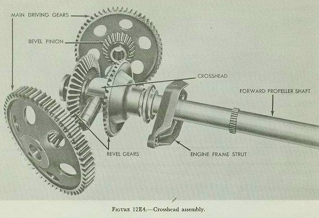 |
| 12E5. Crosshead assembly The crosshead is shown in figure 12E4. Its outer ends are supported in the two A-frames. Bronze bushings fit over the two crosshead shafts. These bushings serve as bearings for the main drive gears and bevel pinions. (Each drive gear and pinion combination is machined from a single forging.) In figure 12E4 the bushings are in place on the crosshead. Note the spiral oil grooves on the surface of the bushings. Notice also, to the right of the strut, a small pinion gear machined on the outside of the forward propeller shaft. This pinion supplies the power that drives the steering mechanism. The after propeller shaft passes through the cross-head in a floating bronze bushing. The forward bevel gear is keyed to the after (inner) propeller shaft; the after bevel gear is keyed to the forward (outer) propeller shaft. The outer propeller shaft turns in a bearing in the engine frame strut. This bearing supports the shaft radially; it prevents any motion at right angles to the torpedo axis. Between the after bevel gear and the crosshead are a bearing washer and a thrust bearing. 12E6. Engine thrust As the propellers turn, they develop a thrust, or pushing force. They transmit this thrust to their shafts. To drive the torpedo through the water, this thrust must be taken from the propeller shafts and applied to the shell of the torpedo. This is done in three ways: The after bevel gear is driven by the two bevel pinions. Because of the slope of the gear teeth, the turning force of the bevel pinions tends to push the bevel gear aft. But the thrust of the forward propeller tends to push the bevel gear forward. The thrust of the propeller is stronger than that of the gears. A part of the thrust of the forward propeller therefore goes through the after bevel gear to the bevel pinions, and from there to the crosshead. The rest of the thrust from the forward propeller is applied to the crosshead directly, through a thrust bearing and washer. The crosshead transmits the forward thrust through the A-frames and the turbine bulkhead to the shell of the torpedo. The after propeller shaft applies its thrust to a thrust bearing mounted on the after side of the turbine spindle casing. The spindle casing carries the thrust through the A-frames to the turbine bulkhead. 12E7. Engine balancing Any rapidly rotating body develops a gyroscopic action, and resists any force that tends to turn its axis of rotation. The engine parts of a Mark 15 torpedo rotate fast enough to develop a considerable gyroscopic action. To keep this action from interfering with the steering mechanism of the torpedo, the main engine is balanced. The gyroscopic force of each of the principal rotating parts is balanced by the force of a similar part rotating in the opposite direction. For example, the gyro action of the first turbine wheel is balanced by that of the second. Other pairs of counter-rotating parts include the turbine pinions, the main drive gears, the bevel pinions, and the bevel gears. |
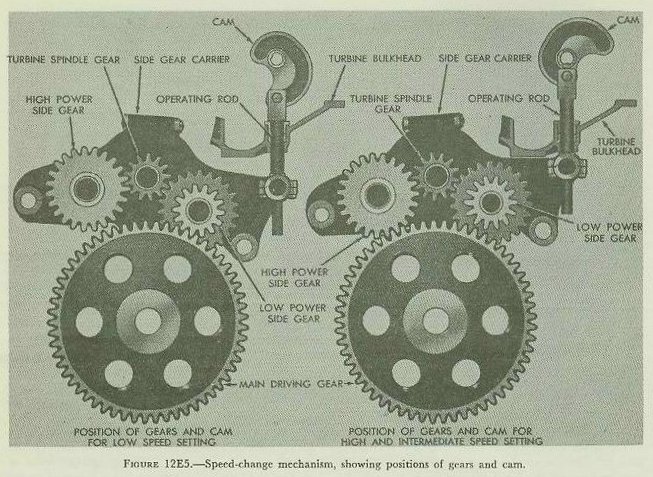 |
| 12E8. Side gear assembly As previously explained, the speed-change mechanism of the Mark 15 torpedo includes a means for changing the gear ratio in the main engine. This is accomplished by interposing idler gears, called side gears, between the turbine pinions and the main drive gears. Figure 12E5 is a diagram representing the side gears in the low-speed setting (left) and the high-speed setting (right). The side gear carrier is mounted on the turbine spindle casing. When the speed-setting socket is turned the cam rotates, moving the operating rod backward or forward. The operating rod turns the side gear carrier, so that either the high-power or the low-power side gear may be engaged with the main drive gear. The turbine spindle gear (turbine pinion) is engaged with both side gears at all times. In the left-hand diagram (figure 12E5), the high-power side gear is turning idly; the main drive gear is driven through the low-power side gear. The right-hand diagram shows the opposite condition. Figure 12E5 shows only 1 set of side gears. There are, of course, 2 such sets-1 for each of the two turbine pinions and main drive gears. This can be seen in figure 12E1, in which the 2 low-power side gears are meshed with the 2 main drive gears. |
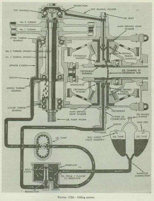 |
| 12E9. Oiling system The after propeller shaft bearings are lubricated by grease, which has been applied under pressure to seal the afterbody against entry of sea water. All other bearings associated with the main engine, as well as all the gear teeth, are supplied with oil throughout the torpedo run. Figure 12E6 is a diagram of the oiling system of a Mark 15 torpedo. Oil flows from the two oil tanks to the reservoir. The reservoir ensures a steady supply of oil for the pump. The pump which is driven by a worm on the bottom of the second turbine spindle, operates at constant pressure. Excess oil is bypassed, and returns to the reservoir. The pump forces oil through 2 separate outlets-1 for the turbine spindle bearings and 1 for the crosshead. The oil that flows to the crosshead lubricates the crosshead bushing, the driving pinion bushings, and the top bearing of the second turbine. The pump does not force oil directly to the gear teeth, or the strut bearing, or the propeller shaft thrust bearing. But oil leaks out constantly past the main driving gear washers, and past the crosshead bushing. The turning gears whip this oil into a spray, or fog. This oil fog lubricates all the parts that aren’t supplied directly by the oil pump. |
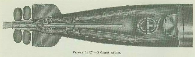 |
| 12E10. Exhaust system Figure 12E7 shows the exhaust system of a Mark 15 torpedo, looking down from the top. The two tubes carry exhaust gases from the space above the turbines to the tail section. Near the after end of the afterbody, each tube separates into two branches. (In figure 12E7, the lower branch of each tube is hidden.) The exhaust gases enter the tail section through four openings in the after bulkhead of the afterbody. When the torpedo is under way, the main engine space is filled with a fog of oil. If this fog is allowed to mix with the hot exhaust gases it will burn. The torpedo will then leave a heavy wake of smoke. This is prevented in two ways: 1. Under the turbines, attached to the top engine frame, is a sheet steel pan called the turbine oil guard. This pan, together with thin horizontal and vertical bulkheads, keeps oil fog out of the exhaust system. 2. Above the upper turbine spindle bearing is a baffle, called the oil deflector ring. This ring keeps the oil in the spindle bearing from entering the turbine exhaust space. |