| NAVAL ORDNANCE AND GUNNERY CHAPTER 12 TORPEDOES |
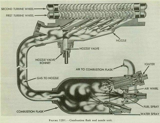
| D. Superheating System of a Mark 15 Torpedo 12D1. General Figure 12D1 is a diagram of the superheating system of a Mark 15 torpedo. The system consists of the combustion flask, the devices through which air, fuel, and water enter the flask, the igniter, the nozzles through which combustion gases flow to the turbine blades, and the nozzle valve. All of these parts are mounted on the forward face of the turbine bulkhead. 12D2. Functional description As previously explained, the compressed air in the torpedo’s air flask has enough energy to propel the torpedo for a short distance at moderate speed. But both speed and range are increased considerably by superheating the compressed air. This is done in the combustion flask, where fuel is burned in a stream of working-pressure air. In burning, the liquid fuel is converted to gases, which add their volume to that of the compressed air. The heat of combustion increases the pressure, and therefore the speed at which the combustion gases strike the turbine blades. The water that is sprayed into the flask to cool it turns to steam, and adds to the volume of gases. The water, of course, contributes no energy to the system. But it does take energy that would otherwise be wasted as heat, and makes it do useful work. When the torpedo’s starting valve opens, air passes through the reducing and restriction valves, and into a fitting at the end of the combustion flask. A part of this air passes out through a pipe to the air strainer body, to operate the depth and steering engines. The rest of it enters the flask through a whirl or premixer, which gives it a spinning motion. Air from the reducing valve also flows to the fuel and water compartments, and forces fuel and water into the flask. As previously explained, the air pressure drops slightly as the air passes through the restriction valve. The pressure in the fuel and water compartments is therefore higher than that in the combustion flask, thus insuring a continuous flow of fuel and water into the flask. The fuel spray, mounted in the center of the air whirl, delivers fuel in the form of a fine mist. The fuel and the whirling air mix thoroughly, and the igniter starts them burning. Once ignited, the fuel and air mixture continues to burn without any further help from the igniter. The igniter burns out after about 6 seconds. Water is delivered to the combustion flask through two water sprays. (Only one of them is visible in figure 12D1.) The water spray holders are longer than the fuel spray holder, and are set deeper into the combustion flask. That gives the air-fuel mixture a chance to burn before water is sprayed into it. The hot combustion gases pass at high velocity from the combustion flask to the nozzle unit. They strike the blades of the first turbine wheel, and start it spinning. The gases are deflected from the blades of the first turbine wheel and strike those of the second, and spin it in the opposite direction. The nozzle valve (figure 12D1) is a part of the speed-change mechanism. Note, in the illustration, that combustion gases pass through five separate nozzles before they reach the first turbine wheel. When the nozzle valve is raised a short distance it closes 3 of the nozzles, leaving only 2 of them open. When raised all the way, the valve closes all of the nozzles but one. |
 |
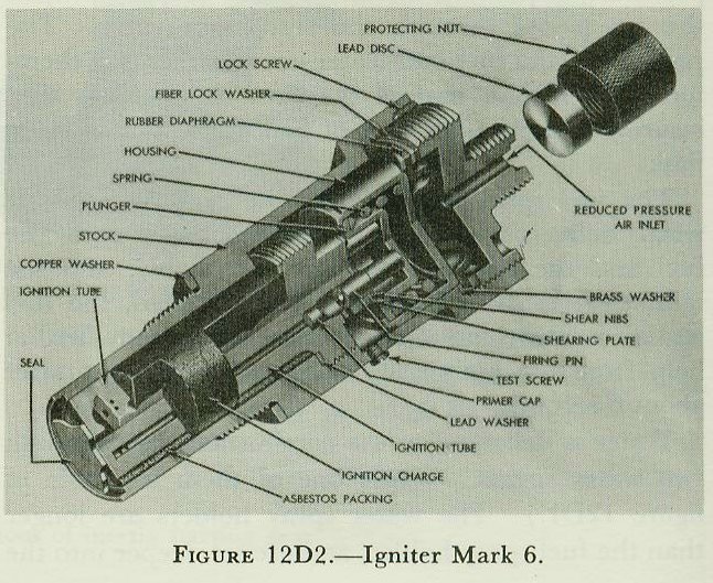
| 12D3. Igniter The igniter may be seen in figure 12D1, screwed into place in a threaded opening in the combustion flask. During transportation or overhaul of the torpedo, a dummy igniter is used in this opening to keep out drift and moisture. During preparations for firing, the dummy is removed and replaced by the real igniter. A protecting nut and lead disc are then removed from the outer end of the igniter, and an air pipe from the reducing valve is connected to it. Figure 12D2 shows a cutaway view of the igniter. When the torpedo is launched, air from the reducing valve enters through the reduced-pressure air inlet at the outer end. Air pressure, acting through the rubber diaphragm, presses down on the housing. The sheer nibs hold the housing in place until pressure in the igniter builds up to about 250 psi. Then they suddenly give way. The housing and the firing pins snap down, and fire the primer caps. Flame from the caps spurts down through the two ignition tubes, blows out the end seal, and lights the ignition charge. The ignition charge burns from the bottom upward. |
 |
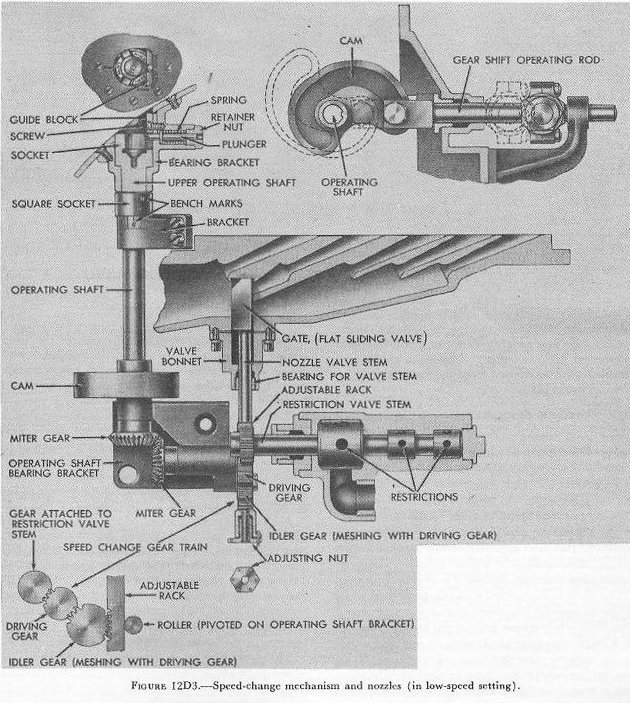
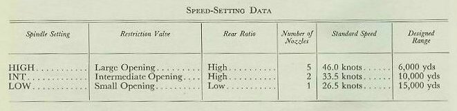
| 12D4. Speed-change mechanism The speed change mechanism is not a part of the superheating system, but is closely associated with it. The mechanism is so designed that the torpedo tube crew can change the speed at which the torpedo will run by turning a single shaft accessible from outside the torpedo. The torpedo tube barrel is provided with a spring-loaded spindle for this purpose. This spindle can be forced down into the socket of the speed-setting shaft of the torpedo. The torpedo speedcan thus be changed at any time up to a few seconds before launching. Figure 12D3 is a diagrammatic view of the speed-change mechanism of a Mark 15 torpedo. The operating shaft is at the left of the figure, and the setting socket at the top of the shaft. Turning the shaft does three things: 1. It changes the size of the restrictions in the restriction valve. 2. It changes the number of nozzles covered by the nozzle valve. 3. It changes the gear ratio of the main engine. The operating shaft, through its associated gear train, turns the restriction valve stem. One of the gears in this train meshes with a rack on the lower end of the nozzle valve stem, so that turning the operating shaft will raise or lower the nozzle valve. A cam is mounted- on the operating shaft near its lower end. The insert at the upper right of figure 12D3 shows how the cam changes the rotary motion of the shaft to a fore-and-aft motion of the gear shift operating rod. (The gear-shift mechanism will be described later.) Speed-setting data for the Mark 15 torpedo is summarized in the following table. |
 |
 |