| GENE SLOVER'S US NAVY FIRE CONTROL PAGES NAVAL ORDNANCE AND GUNNERY, VOLUME 2 CHAPTER 28 ANTISUBMARINE WARFARE |
| HOME INDEX Chapter 28 Antisubmarine warfare A. General B. QHBa scanning sonar equipment C. Controling the attack D. OKA-1 Sonar resolving equipment E. Depth-determining sonar equipment |
| E. Depth-Determining Sonar Equipment 28E1. Introduction No one particular type of depth-determining equipment will be described in this article. The various types employed at the present time (the QDA being an example) all have similar functions when used with the OKA-1 sonar-resolving equipment. That is, they- 1. Measure and transit to other units the value of sonar depression Eq. 2. Record and transmit to other units the value of target depth Hq. 28E2. Description Most of the depth-determining equipments now employed in the fleet use the same basic principle for computing target depth. This principle involves measuring the depression angle of the sound beam to the target, then resolving the speed of sound in water along that sound beam into its component in a vertical plane. Then this component of the velocity of sound in water is used to control the stylus speed of a recorder, with the excursion of the stylus starting at the instant the sound is transmitted into the water and the stylus marking a recorder paper when the echo is received. The recorder paper moves from one roller onto another, so that there will always be a new measurement of depth whenever an echo is received from the target on the depth-determining sonar equipment. The depth-determining sonar uses a tiltable transducer or a fixed transducer with a scanning receiving beam for measurement of the depression angle of the sound beam. If there were no refraction of sound in water, the sound beam would follow the straight line connecting own ship and target. However, as pointed out previously, temperature, pressure, and salinity differences will cause variations in water density which, in turn, will result in refraction of the sound beam. The effects of salinity and pressure variations are minor and will be neglected in this discussion. The effect of temperature variations, on the other hand, is appreciable and will be discussed in more detail. The temperature varies rather irregularly, due to currents and sea conditions. Generally speaking, however, it remains relatively constant down to a certain depth (known as the layer depth), then becomes rapidly cooler in a region known as the thermocline, and finally is relatively constant (but cooler) again until another thermocline is reached. The effect of thermoclines (i. e., regions of steep temperature gradients) upon sound beams is twofold. In the first place, because of the change in water density at the thermocline, sound beams other than those normal to the thermocline will be refracted downward (toward the normal) as they enter the cooler, more dense water. Secondly, the speed of sound is decreased upon entering the water of lower temperature. Because of these effects, the depth of the thermocline below the surface of the water (the layer depth) must be measured every few hours if accurate determination of target depth Hq is going to be possible. The measurement is accomplished by use of an instrument known as the bathythermograph (B/T). The B/T, which contains pressure- and temperature-measuring devices, is lowered over the side of a surface ship on the end of a long wire. During its descent it records pressure (which is a measure of depth) versus temperature on a slide which can be placed in a viewer and read when the B/T is recovered. |
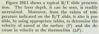 |
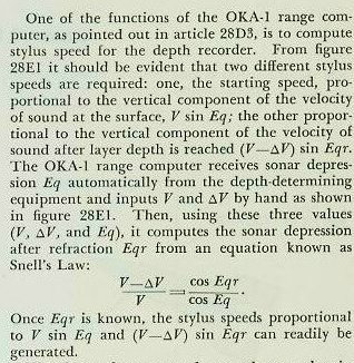 |
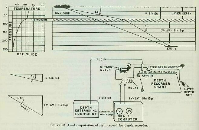 |
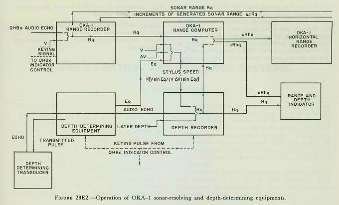
| The change from one stylus speed to another in the depth recorder is accomplished, as shown in figure 28E1, by positioning a contact maker at a point representing layer depth. The moving stylus, upon striking this contact maker, will trip a relay in the stylus-speed circuit which will change the speed from one proportional to V sin Eq to one proportional to sin Eqr. The audio response from the depth-determining equipment is fed through the stylus in a way that marks the sensitized paper whenever a target echo is received. Basically, the operation of the depth recorder is the same as that of the OKA-1 range recorder except for the two speeds involved in stylus excursion. 28E3. Summary of the OKA-1 and depth-determining system Figure 28E2 illustrates, in simplified schematic form, the operation of the various units of the OKA-1 sonar-resolving and depth-determining equipments. |
 |