| GENE SLOVER'S US NAVY FIRE CONTROL PAGES NAVAL ORDNANCE AND GUNNERY, VOLUME 2 CHAPTER 28 ANTISUBMARINE WARFARE |
| HOME INDEX Chapter 28 Antisubmarine warfare A. General B. QHBa scanning sonar equipment C. Controling the attack D. OKA-1 Sonar resolving equipment E. Depth-determining sonar equipment |
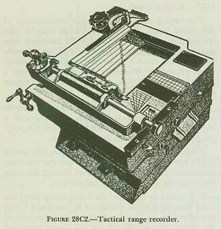
| C. Controlling the Attack 28C1. General Sonar can search out the target, but course-to steer and firing time must be determined by other instruments. Two such instruments are the tactical range recorder (TRR) and the antisubmarine attack plotter (AP). 28C2. Tactical range recorder (TRR) The tactical range recorder (TRR) produces a time/range plot of target echoes on chemically sensitized paper by means of a moving stylus. See figure 28C1. The stylus moves across a chart at a speed proportional to half the speed of sound in water and the chart paper moves at a constant speed in a direction perpendicular to the stylus motion. The tactical range recorder accomplishes the following functions: 1. It provides a means for measuring sonar range Rq and sonar range rate. 2. It provides a means of determining firing time (i. e., the time when Tud = 0) for either the stern-dropped (depth-charge) attack or the throwing-weapons (hedgehog) attack. 3. It provides a visible plot of the audio reception to help identify target echoes. 4. It may be used to control the keying circuit of the QHBa scanning sonar equipment. The TRR has two range scales. The 0-3750 range scale is etched on a black metal plate on the top of the recorder, above the window over the chart. The 0-1500 yard scale is inside the window just above the chart; it is etched on clear lucite, and illuminated by an inside light. Sonar range Rq is read by noting the appropriate scale reading of the last stylus mark made on the paper. Therefore, when on long scale, the entire width of the chart paper represents 0-3750 yards, while on short scale it represents 0-1500 yards. (Both the QHBa indicator control and the OKA-l range recorder have the same scale arrangement.) |
 |
 |
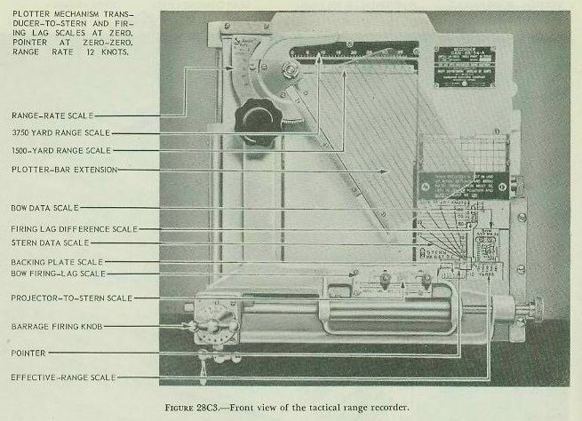 |
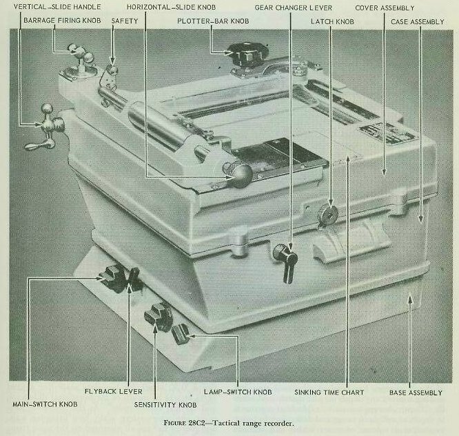
| In order to measure sonar range and sonar range rate (discussed later) for both scales, using the same chart paper, it is necessary to have a range scale, stylus speed, and chart motion speed for each scale. A gear changer lever; (shown in fig. 28C2) on the right side of the recorder selects the proper stylus and paper speed for each scale. Just above the top of the chart paper is a pointer, commonly called the fly back, whose position across the chart is controlled by the flyback lever (fig. 28C2) on the front of the TRR. When the stylus reaches this flyback, it stops its recording stroke and is returned quickly to the left to start another recording excursion. The recorder sends a keying signal to the QHBa scanning sonar equipment at the instant it starts its recording motion. The position of the flyback therefore determines the keying interval of the QHBa scanning sonar equipment. On top of the recorder is a plotter bar which is rotatable and has a lucite extension on which are etched a series of lines parallel to the plotter bar. See figure 28C3. By aligning one of these lines with the traces on the chart, the slope of the range line and hence the sonar range rate may be measured. This plotter bar is also used to determine firing time. As the range to the target closes, the traces on the plotter chart will move to the left. When the leading edge of the trace is under the firing line, it is time to fire the charge. |
| As will be seen in figure 28C3, there are several scales used to set in the various values concerned with determining the time to fire a hedgehog barrage or depth-charge pattern. The majority of these scales are set for certain physical characteristics of the ship and are not changed as the attack progresses. These are- 1. Bow firing-lag scale (inscribed FIRING LAG SEC.). On this scale is set the total time interval between the moment the A/S officer orders “Fire” and the instant the hedgehogs hit the water-dead time (Tg) plus time of flight (Tf). The dead-time factor in this setting is determined by a time study on each ship; the time-of-flight factor, from appropriate range tables. 2. Firing-lag difference scale (upper right scale inscribed 0, 6, 12). The purpose of this scale is to eliminate the necessity of changing the setting on the bow firing-lag scale every time the ship changes from a H/H to a D/C attack. The proper setting on this scale removes the error of an “earlier firing time” that would exist in a D/C attack after the bow firing-lag scale is set equal to Tf + Tg for H/H. In order to maintain the correct time relationship between the two types of attack, it is necessary to consider the different “dead times” for H/H and D/C. If Tf + Tg (for H/H) is set on the bow firing-lag scale, it is apparent that the same value should be set on the firing-lag difference scale in order to offset the Tf + Tg which would be erroneous for D/C. At this point the setting on both scales is the equivalent of Tf + Tg for H/H equals Tf+ Tg=0 for D/C. Since more dead time for D/C necessitates earlier firing, the stern-data scale is moved UP the firing-lag difference scale a distance equal to the dead time (for D/C) from the original position (Tf + Tg for H/H). The SETTING for the firing-lag difference scale is therefore calculated from the formula Tf + Tg (for H/H) - Tg (for D/C). Example: For H/H, Tf = 8 sec.; Tg = 3 sec. For D/C, Tg = 5 sec. Setting on bow firing-lag scale 8 + 3 - 11 sec. SETTING ON FIRING-LAG DIFFERENCE SCALE 8 + 3 - 5 = 6 sec. 3. Projector-to-stern scale (inscribed PROJ. TO STERN). On this scale is set the distance in feet from the sonar transducer to the depth-charge racks on the stern (i. e., the parallax base line P1). It is obtained from ship’s plans and is constant for each ship. 4. Backing-plate scale (located beneath RE scale and inscribed FEET). The distance in feet from the sonar transducer to the depth-charge racks on the stern is set on this scale to remove the effect of the projector-to-stern scale setting when firing throwing weapons. 5. Effective-range scale (inscribed RE). On this scale is set the range of the hedgehog missiles Re as determined by the conditions existing at the time. 6. Zero-zero scale (to the left of RE scale and inscribed 0, 6, 12). This scale is used for alignment purposes. In addition to the more or less permanent scales above, there are also two scales whose settings may have to be changed as an attack progresses. They are- 7. Stern-data scale (inscribed STERN). On this are set own ship’s speed of attack (So) and the sinking time (Td) (labeled D C. SETTING SECONDS) for depth charges. The ship’s speed is obtained from the pitometer log, and the sinking time depends on the target depth. The sinking rate for all types of depth charges has been so tabulated that the sinking time to any depth may be determined readily. Depth charges are set to explode at a pattern in depth as well as in range and deflection, in order to enclose a volume of water which will include the submarine. The measured or assumed depth which is the mean of the pattern is used in making this setting. 8. Bow-data scale (inscribed Bow). On this are set own ship’s speed of attack (So) and the sinking time (Td) for hedgehogs. As in a depth-charge attack, the ship’s speed is obtained from the pitometer log and the sinking time is calculated from the known sinking rate of the hedgehogs to the measured or assumed depth. The settings on the stern- and bow-data scale are made by means of the data-scale indicator. This indicator is a lucite arm which is attached to the horizontal slide bar; its index, as illustrated in figure 28C3 is a “dot.” This index or “dot” is positioned over the intersection of the proper data lines (So and Td) on either the stern-data scale (for a DJC attack) or bow-data scale (for a fixed H/H attack) by means of the horizontal slide knob and vertical slide handle. As the data-scale indicator, projector-to-stern scale, bow firing-lag scale, and plotter bar are all mounted on the same frame and hence all move together whenever the horizontal slide knob or the vertical slide handle is turned, it can be seen that movement of any of the above scales will move the “dot” away from its proper position (intersection of So and Td) on the bow-data or stern-data scale or move the intersection of So and Td out from under the “dot.” The situation is then corrected by movement of the horizontal slide knob or the vertical slide handle which moves the “dot” back over the original intersection; consequently, the firing line on the plotter bar is moved closer to or farther away from the traces on the chart paper. The manner in which a setting is made on any of the more-or-less permanent scales can be seen in figure 28C3. Briefly, a value is set on the- 1. Bow firing-lag scale, by moving the projector-to-stern scale vertically. 2. Firing-lag difference scale, by moving the stern-data scale vertically. 3. Projector-to-stern scale, by moving it horizontally. 4. Backing-plate scale by moving the effective-range scale (RE) horizontally. 5. Effective-range scale by moving the bow-data scale horizontally. As previously mentioned, these settings on the more-or-less permanent scales (listed in 1-5 above) all serve to position either the stern- and bow-data scales or the data-scale indicator index with respect to the origin of the chart paper. Consequently, they either increase or decrease the time remaining until firing should occur. For example, consider the effects of the bow firing-lag scale and firing-lag difference scale settings on firing time. From figure-28C3 it can be seen that, once the data-scale indicator index is positioned at a certain point, an increase in the bow firing-lag scale setting (a change in Tf + Tg from 9 to 12 seconds, for example) will move the data-scale indicator index down (as viewed in the illustration). Hence it will be necessary to drive the index back up to its original position by turning the vertical slide handle. Moving the index back up, in turn, will result in the plotter bar and its extension also moving up, closer to the traces, with the result that firing time for H/H will occur sooner. Part of this motion of the plotter bar (the part corresponding to the Tf setting for H/H and any difference in Tg between H/H and D/C) will result in an incorrect firing time when firing depth charges; consequently, we must counteract this effect by setting a value on the firing-lag difference scale as explained previously. This is done physically by moving the stern-data scale until the index at the upper right corner of the scale is opposite the value of Tf + Tg (for H/H) - Tg (for D/C). This downward motion of the stern-data scale (if the index were originally at 0 seconds) will necessitate downward motion of the data-scale indicator index which, in turn, will result in the plotter bar’s being moved away from the traces, thus delaying the firing of depth charges from the point they would have been fired had this time difference between H/H and D/C not been considered. The idea of calculating settings for both the above scales can be explained from the point of convenience and efficiency, should a H/H and D/C attack be conducted on the same target. It is obvious why H/H and D/C cannot be fired at the same Tud = 0, and it is also apparent that changing the setting in seconds on the bow firing-lag scale every time you changed from H/H to D/C would accomplish the same result. Therefore, instead of continuously changing one scale, permanent settings are set on both scales making it necessary to move the data-scale indicator index only from the bow-data scale intersection of So and Td to the appropriate setting on the stern-data scale when changing from H/H to D/C attack. Similarly, it could be shown that (1) an increased projector-to-stern scale setting would delay firing of depth charges a desired amount; (2) a corresponding increase in the backing-plate scale setting would compensate for this delay when firing fixed hedgehogs; and (3) an increased effective-range scale setting would result in an earlier firing time. Because the tactical range recorder takes into consideration only the range aspects of the problem, the conning officer must rely on other sources for assistance in determining the proper course and speed to use to attain a firing position. Assistance from CIC, various “thumb rules” determined from experience, and a “seaman’s eye” are the general practice. There is a barrage firing knob on the horizontal slide bar which is used to fire a pattern in range. This knob is kept in center position 3 during the approach. When the range closes to about 500 yards, it is moved to position 1, which moves the plotter bar a fixed amount to the right, thus making the firing time for the first charge of the pattern earlier than the center. When the firing line is over the leading edge-of the traces, the first charge is fired and the knob shifted to position 2, which moves the firing line to the left. These steps are then repeated until all five charges have been fired. A fixed throwing-weapons (hedgehog) attack is conducted in a similar manner, except that the bow-data scale is used and the barrage firing knob is left on position 3 (the position which corresponds to a Tud of zero). 28C3. Attack plotter As pointed out previously, the Tactical Range Recorder provides a means of determining the time to fire a D/C barrage or H/H pattern, based on an analysis of range and range rate data. But it makes no provision for determining the course to steer (cCo) to reach the firing position. With slow-speed submarines, the various methods of estimating this course were accurate enough to include the submarine in the D/C or H/H pattern. The advent of higher submerged speeds for submarines made necessary more precise methods for determining attack tactics. The next step in the evolution of ASW fire control equipment was the Antisubmarine Attack Plotter (ASAP) Mark 1. This instrument makes it possible to estimate more accurately the course which should be steered (cCo) to reach the desired firing position, as well as to determine the time at which firing should occur (Tud 0). However, it was designed only for use when firing depth charges or fixed hedgehogs. It was not designed for trainable attacks. Consequently, no mention of projector train order B’gr or advance range R2 will be made in this discussion. |
 |
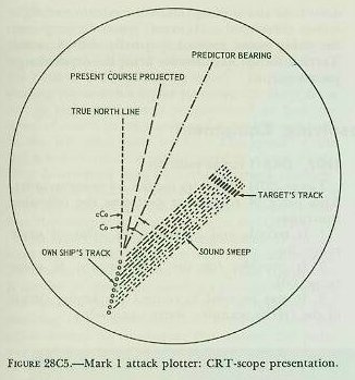 |
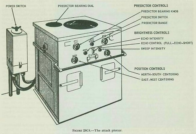
| The Attack Plotter, shown in figure 28C4, is an electronic instrument which displays on the face of a cathode-ray tube a geographical picture of own-ship and target motion. The own-ship indication, as illustrated in figure 28C5, is a single bright dot that moves across the scope according to the true course and speed of own ship, as received automatically from the gyro compass and pitometer log. There are N-S and E-W controls on the front of the instrument for making initial settings of own ship’s position. These are similar to the controls used to position the “bug” on a Dead Reckoning Tracer (DRT). In effect, the Attack Plotter is an electronic DRT which shows own-ship motion automatically, as well as target position relative to own ship. The target position, which is indicated on the scope as a bright spot, is controlled by the audio section of the QHBa Scanning Sonar Equipment. As the sound beam is projected through the water a faint line is visible on the scope, originating at own ship and proceeding in the direction the audio section is trained. If the beam strikes a target and an echo is returned, the trace is momentarily brightened so as to display on the scope a bright spot representing the target. The picture of relative motion thus presented assists the operator in determining the proper course to steer to reach the firing position. Another feature of the Attack Plotter which enables the operator to better estimate the course to be steered (cCo) and the time at which to fire ahead-thrown weapons (Tud = 0) is the “predictor line.” |
| This is a bright line which momentarily flashes on the face of the scope immediately after own ship’s spot, and just before the sound sweep starts. The direction and length of this line can be adjusted by the operator. The true bearing of the predictor line is controlled by a Predictor Bearing Knob on the front of the Attack Plotter, and read on a dial on the top. The length of the predictor line, or Predictor Range, is determined by a three-position knob known as the Predictor Switch. When this switch is in the OFF position, the predictor line does not appear on the scope; when it is set to the “1000” position, the length of the predictor line is fixed at 1,000 yards (4 inches on the scope); and when it is placed in the “RANGE” position, the length of the predictor line is governed by the three Predictor Range Controls which, by appropriate combinations, permit the setting of any range from zero to 580 yards. Normally the Predictor Switch is kept on RANGE. However, the 1,000-yard position is useful on occasions when own ship and target are separated by more than the 2500-yard (10-inch) width of the scope. In such cases, own ship can be placed off the scope and still be conned toward the target by means of the long predictor line. The OFF position also is useful at times, since it permits the presentation of targets closer than 150 yards. Such targets can not normally be seen when the predictor line is shown on the scope. In order to conduct an attack using ahead-thrown weapons, the following procedure should be used: 1. By means of the N-S and E-W controls on the front of the instrument, orient own ship and target so that the target will be headed for the center of the scope. This is done so that a continuous plot of own ship and target will be possible without the necessity of “repositioning” during the attack and thus interrupting the continuity of the plot. 2. By means of the Predictor Range controls, adjust the length of the predictor line to the effective range of hedgehog missiles when controlled by the Attack Plotter. (The computation of this effective range will be discussed in more detail later.) As previously stated, the true bearing of the predictor line may be controlled by the operator. Using the Predictor Bearing knob, estimate a course which when steered by own ship will result in a situation in which the end of the predictor line will pass through the predicted position of the target. It will be recalled that from the instant the word to fire is given, there will be an elapsed dead time Tg until the weapon is fired, a time of flight Tf until the pattern lands, and a sinking time interval Td until the H/H’s sink. If this total time is, for example, 20 seconds, the target will move during this 20-second period and the H/H’s must be at the predicted position at the end of this time. The true bearing of the predictor line is automatically transmitted to an indicator on the bridge in front of the helmsman as the course to steer, or own-ship course order cCo. The target’s course can be estimated on the scope from the target’s apparent motion, and target speed can be approximated by comparison with own ship’s speed, bearing in mind that the scale of the scope is about 250 yards per inch. Continual adjustments of own-ship course order can be made as the range closes, so as to compensate for target maneuvers. The time at which firing should occur (Tud = 0) is reached at the instant the end of the predictor line leads by a proper amount the “pip” indicating the target position, or, more specifically, when it leads the target by an amount (expressed in inches) equal to target speed S times the quantity (Tg + Tf + Td). From the above it may be seen that the fire control problem is quite accurately solved from the range standpoint, but leaves much to be desired as regards determining the proper approach course. The accuracy of the proper approach course is largely dependent on the operator’s understanding of the relative motion of own ship and target. In conducting a depth charge attack, the same general principles are used to arrive at the firing position. In this case own ship must cross over the predicted target position before the charges are dropped. In figuring the predicted position, only dead time and sinking time are used; time of flight is not considered. However, when arriving near the firing point, control is usually shifted to the Tactical Range Recorder for firing the depth charge pattern. |