| GENE SLOVER'S US NAVY FIRE CONTROL PAGES NAVAL ORDNANCE AND GUNNERY, VOLUME 2 CHAPTER 28 ANTISUBMARINE WARFARE |
| HOME INDEX Chapter 28 Antisubmarine warfare A. General B. QHBa scanning sonar equipment C. Controling the attack D. OKA-1 Sonar resolving equipment E. Depth-determining sonar equipment |
| D. OKA-1 Sonar-Resolving Equipment 28D1. Introduction The 0 KA- 1 sonar-resolving equipment consists of the following three major units: 1. Range recorder. 2. Range computer. 3. Horizontal range recorder. Either the TRR or the OKA-l Range Recorder can be used with the QHB scanning sonar equipment to provide the keying pulse. 28D2. OKA-1 range recorder Figure 28D1 illustrates the OKA-1 range recorder. This piece of equipment performs the following functions: I. It records and transmits the value of sonar range Rq. 2. It provides for the measurement of sonar range rate. 3. It may be used to control the keying circuit of the QHBa scanning sonar equipment. The recorder mechanism (as shown in fig. 28D1) is made up of a strip chart device employing moist, chemically sensitized paper which moves slowly at a constant speed in a direction perpendicular to the path of a reciprocating stylus. During its recording motion this stylus traverses the chart from left to right at a speed proportional to half the speed of sound in sea water, and is rapidly returned to the left after each stroke. The speed of the stylus is corrected for actual speed of sound conditions determined from bathythermograph readings. (See article 28E2.) This correction is set with a knob and dial on the OKA-l range recorder. Note that this correction is not made in the QHBa. |
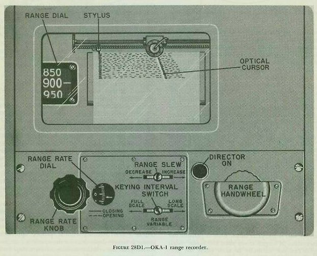 |
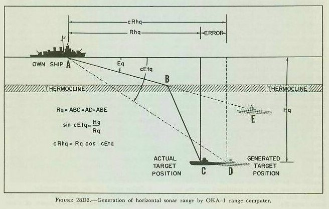
| The stylus starts its recording motion at the instant the transmitted pulse leaves the transducer. The audio signal received by the QHBa equipment is applied to the stylus, causing a passage of current through the paper when an echo is received and resulting in a visible mark. Therefore, since the stylus started its motion at the instant the pulse was transmitted and moves at a rate proportional to half the speed of sound, the distance from the starting point to the mark is a measure of the sonar range to the target. Determination of the sonar range to the target is accomplished by an optical cursor (light beam) which projects a cursor image on the recorder chart. This image is moved across the chart to the position of the last target mark by a synchro system which provides sonar range Rq to the OKA-l range computer and, in addition, indicates the value of this range on a dial on the recorder. The optical cursor is rotatable, so that it may be lined up with a series of range marks as the paper moves down the recorder at a constant speed which represents time. The slope of the optical cursor, when properly lined up, is therefore a measure of the rate of change of sonar range. The controls for operating the OKA-l range recorder are located on both the top panel and the front panel of the instrument. Those on the top panel are shown in figure 28D1 and are described in the paragraphs that follow. 1. Range slew, range handwheel, range dial. The range slew and range handwheel move the optical cursor (light beam) across the scale horizontally. The slew is used to position the cursor initially on a target; the handwheel, to provide the attack director with rate control corrections. Any horizontal motion of the cursor is recorded on the range dial located at the left of the recorder chart. Whenever the cursor is properly positioned over the target, this dial indicates the instantaneous value of sonar range Rq. 2. Range-rate knob and dial. These are shown at the lower left corner of figure 28Dl. The range-rate knob controls the slope of the optical cursor as well as the operation of the cursor-positioning synchro system mentioned above. When the knob is turned so that the cursor assumes a vertical position, the reading on the range-rate dial will be zero and the synchro system will not move the cursor. This is the normal condition when slewing to a new target. However, once a target is acquired and the optical cursor is aligned with a series of range marks which collectively have a definite slope, the range-rate dial will indicate a value of range rate corresponding to that slope. Moreover, the value of range rate will cause the synchro system to position the cursor continuously over the range marks. As long as the actual range rate of the target does not change, the target will be tracked automatically and correct values of Rq will be transmitted to the OKA-l range computer. 3. Keying-interval switch. The switch controls the keying interval of the QHBa, and thus the stylus speed and chart scale of the range recorder. This switch has three positions: LONG SCALE, FULL SCALE, and RANGE VARIABLE. In the LONG SCALE position, the chart width represents 3,750 yards and the stylus traverses the full width thereof before hitting the fixed flyback, which returns the stylus rapidly to the left. In the FULL SCALE position, the chart width represents either 3,750 yards or 1,500 yards depending upon the location of the cursor. The change of scales occurs automatically as the cursor passes about the 1,450 yard point of the scale. Thus when a target closes from say 2,500 yards to 1,450 yards, the recorder automatically shifts to the 1,500 yard scale. In the RANGE VARIABLE position, the scale selection works as in the full scale position. However, the stylus does not traverse the full width of the paper as in the other two positions but is limited to the range of the optical cursor plus 200 yards. The optical cursor carries a variable flyback which in RANGE VARIABLE operation returns the stylus to the left from a position 200 yards greater than cursor position. 28D3. OKA-1 range computer The primary functions of this unit of the OKA-l sonar-resolving equipment are to compute the following quantities: 1. Generated horizontal sonar range cRhq. 2. Stylus speed for the depth recorder. To accomplish the first of these functions, the OKA-1 range computer receives inputs of sonar range Rq from the OKA-l range recorder (as described in the preceding article) and target depth Hq from the depth recorder. With these two in puts, it then generates a value known as the computed target depression cEtq from the relationship: sin cEtq =Hq./Rq. Once cEtq is known through its sine function, the OKA-l range computer can determine the horizontal sonar range from the equation: cRhq = Rq cos cEtq. To understand why the range computer generates horizontal sonar range in this manner, it is necessary to understand more about the refraction of the sound beam mentioned in article 28A3. If there were no refraction of the sound beam, the sonar range Rq would also be the slant range to the target; that is, the sound beam would follow a straight line connecting own ship and target, and Rq would be measured along this line. However, if the sound beam were refracted at some point in its travel by a steep temperature gradient or thermocline, Rq no longer would be the straight-line range to the target, but would be measured along the refracted sound beam. This effect is shown in figure 28D2. The target’s actual position is at point C and Rq is measured along line ABC. |
 |
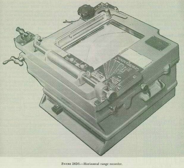 |
| If the OKA-l range computer were to compute horizontal sonar range cRhq from inputs of target depression Eq and a straight-line value of sonar range Rq (= ABE in the illustration), the target’s position would be established erroneously at point E. However, by generating its own value of target depression cEtq from Hq and a straight-line value of Rq (= AD in fig. 28D2), the range computer effectively establishes the target’s position as point D, which is at the correct depth and at a horizontal sonar range cRhq only slightly greater than the true horizontal sonar range Rhq. This approximation of cRhq is possible since the range error (i, e., the difference between cRhq and Rhq) progressively diminishes as the target closes and the amount of sound-beam refraction decreases. The OKA-l range computer accomplishes its second function, the computation of stylus speed for the depth recorder, in conjunction with the depth-determining equipment. The manner in which it does this will be discussed in section E. 28D4. OKA-1 horizontal range recorder The value of horizontal sonar range cR’hq generated by the OKA-l range computer is transmitted not only to a range and depth indicator but also to the OKA-1 horizontal range recorder (fig. 28D3) whose functions are- 1. To record the value of generated horizontal sonar range cRhq. 2. To provide for the measurement of horizontal sonar range rate. 3. To provide a means of determining firing time (i. e., when Tud=0) for either the stern-dropped (depth-charge) attack or the throwing-weapons (hedgehog) attack. In construction and operation, the OKA-1 horizontal range recorder is basically the same as the tactical range recorder, differing from the tactical range recorder in really only two major respects: 1. It employs a nonreciprocating rather than a reciprocating stylus. 2. Its operation is based on an input of generated horizontal sonar range cRhq rather than an input of the audio response from the QHBa equipment. |