| GENE SLOVER'S US NAVY PAGES NAVAL ORDNANCE AND GUNNERY VOLUME 1, NAVAL ORDNANCE CHAPTER 7 TURRET INSTALLATIONS |
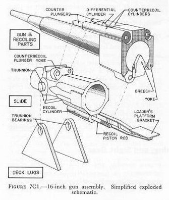
| C. Slide Assembly 7C1. General Although in general the principles of gun mount construction as discussed in chapter 5 apply to the gun slide, and deck lug structures of bag-type turret guns, there are important differences in some details, particularly with respect to the relationship of recoiling and nonrecoiling parts, and the locations of components of the recoil and counterrecoil systems. Therefore, in addition to figure 7C2, which shows in an exterior view the gun and slide of a l6-inch turret gun, figure 7C1 shows, in simplified exploded schematic form, the relationship of recoiling and nonrecoiling parts, and the locations of important parts of the recoil and counterrecoil systems. |
 |
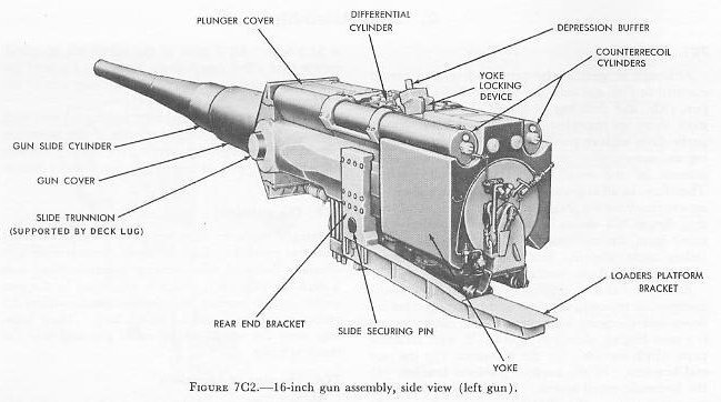 |
| Each gun has a separate slide which is individually mounted in trunnion hearings and is arranged for in dependent elevating movement. The main element is a steel forging, shown in figure 7C2, with attached parts which include: (1) the trunnions, (2) the rear end brackets, (3) the loaders’ platform bracket, (4) the hydraulic recoil system, (5) the counterrecoil recuperator system. (6) the slide-securing device, (7) the yoke-locking device, (8) upper and lower shield plates, and (9) a cylindrical gun cover. The complete assembly is over 33.5 feet long, 79 inches across the trunnions and 116.5 inches high. The total weight is 51.5 tons. All 3 guns in the turret arc identical, except that a few components, found on 1 side of the right and center guns, are on the opposite side of the left gun. Figure 7C2 shows a left gun. The un-slide bore of the steel forging is fitted with 6 bronze liners, each 10 inches wide. The liners are provided with oil grooves and are the bearing surfaces on which the gun slides during recoil and counterrecoil. 7C3. The trunnions Integral with the slide are the 18.5-inch diameter trunnion journals. Each of these journals rests in a specially designed roller-bearing assembly fitted into a deck lug (fig. 7A1) which is supported by the gun girder. Each bearing includes 24 cylinder rollers 2.5 inches in diameter and 3.5 inches long. These bearings carry the weight of the entire gun and take the shock of firing. |
| 7C4. The rear end brackets These brackets are bolted to the left and right side of the slide, One rear end bracket as shown in figure 7C2, provides mounting attachments for the loaders’ platform bracket and the slide-securing pin is seated in an aligned socket in an adjacent gun girder when the gun is at zero degrees elevation. The pin is forced into the socket by means of a handwheel-operated screw. This arrangement serves to relieve the elevating screw and drive gear from the effects of roll, pitch, and vibration when the gun is not being used. Another socket permits locking the gun at 20 degrees elevation while the recuperator air cylinders are being charged. The other rear bracket on the slide (not shown in fig. 7C2) mounts the large pivot pin to which the elevating screw is attached. (Sec article 7D1.) 7C5. Recoil mechanism The recoil mechanism is the conventional hydraulic type and has a single cylinder of 26-inch bore diameter and an over-all length of about 5 feet. It is similar to the one shown in chapter 5. Three equally spaced throttling rods control recoil fluid flow. The recoil is limited to 48 inches (3 calibers), occurs in approximately one-third second. Counterrecoil buffing action is provided by a plunger-dashpot arrangement at the forward end of the cylinder. Liquid displacement from the dashpot occurs through four grooves of variable depth and through the small clearance between the plunger and the dashpot entrance. Buffing action takes place during the last 16 inches of counterrecoil. Two expansion tanks are mounted forward of the recoil cylinders. 7C6. Recuperator The hydropneumatic counterrecoil mechanism consists of two air cylinders mounted on top of the slide and a differential cylinder between them. Its operating principles are discussed in chapter 5. The counterrecoil cylinders, shown in figure 7C2, are about 11 feet long and have an inside diameter of 11 inches. The plungers are hollow cylinders closed at the forward end, and are about 6 feet long and 11 inches in outside diameter. They arc connected to the gun yoke by means of a plunger yoke and two yoke rods which are covered by the plunger cover (fig. 7C2). 7C7. Yoke-locking device This device, which holds the gun in battery when it is not in use, even though pressure in the recuperator is lost, is on top of the slide, at the rear, between the counterrecoil cylinders. A safety link, in the form of an eyebolt, is pinned to the slide. When locked, the safety link rests in a notched bracket on top of the yoke, and a nut on the link is tight against the bracket, holding the yoke and gun securely to the slide. The link is stowed by loosening the nut, swinging the pin up and forward, and clamping it out of the way. If the link is inadvertently left in place when the gun is fired, it will part without damage to the gun, but it must be replaced without delay. 7C8. The shield plates and gun cover The upper and lower shield plates arc located just inside the gun port at the face Plate of the turret. They form a weather and splinter shield for the slide. The gun cover is a 1/2-inch thick cylinder whose inside diameter is slightly larger than the gun’s slide cylinder. It extends through the gun port about seven feet. At its forward end there is a wiping-ring assembly which serves as an oil and weather seal for the gun. A neoprene cover (gun buckler) clamps on the outer end of the gun cover and is attached on the sloping front face of the armor plate, completely enclosing the gun port. |