| GENE SLOVER'S US NAVY PAGES NAVAL ORDNANCE AND GUNNERY VOLUME 1, NAVAL ORDNANCE CHAPTER 5 ELEMENTS OF GUNS AND MOUNTS |
| HOME INDEX Chapter 5 Elements of Gun Mounts A. Introduction B. Features of modern naval guns and mounts C. Conclusion |
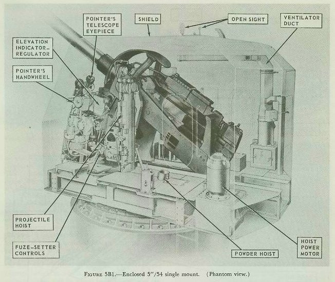
| B. Features of Modern Naval Guns and Mounts 5B1. Common structural features of naval gun mounts Figure 5B1 is a closeup phantom view of a 5”/54 mount Mark 39. Though this particular mark is not the commonest of 5-inch mounts, it is a good example of the conventional type of mount that shows the features with which this chapter is particularly concerned. It differs structurally from most other 5-inch mounts principally in having a longer barrel. There are other differences in power drives and hoist arrangements with which we are not concerned at the moment. Besides showing (as a phantom) the shield which protects the mount, figure 5B1 shows also a number of the major mount components which are essential to its proper functioning but are structurally accessories rather than basic parts. Such units pointed out in figure 5B1 include parts of the elevation controls and power drive (on the left side of this mount), the pointer’s sight telescope, the mount captain’s open sight (in the shield overhead), a ventilator duct (also in the shield), and parts of the hoists and fuze setter. On the other (right) side of the mount are the trainer’s controls and power drive. |
 |
 |
 |
 |
 |
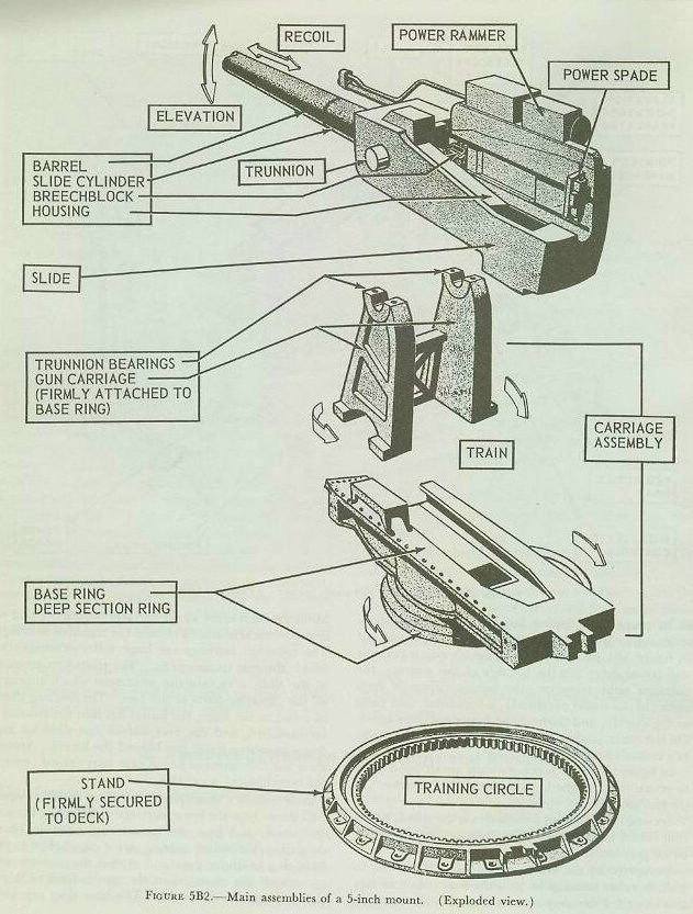
| In figure 5B2 these accessory units are stripped away to reveal what might be considered the “skeleton” of the gun mount. Serving as the mount foundation is the stand, a steel ring bolted to the deck. The training circle is an internal gear inside the stand. Supported by the stand, and capable of rotating in train in roller bearings on it, is the base ring. It may also be called the deep section ring or lower carriage. Mounted on it is the upper carriage, which is a pair of massive brackets braced to hold the trunnion bearings. The trunnion bearings are large roller bearings into which the gun trunnions fit. The trunnions are part of the slide, a rectangular weldment which supports all the elevating parts of the gun. The housing slides in recoil in the slide; the barrel fits into the housing’s forward end, and the breechblock can slide up and down in a breechway just behind the barrel. Arrows show the movement of which each part named (except the breechblock) is capable. |
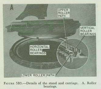
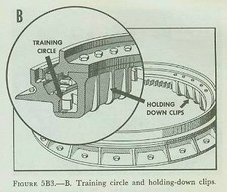
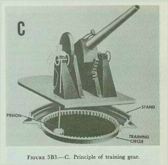
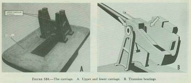
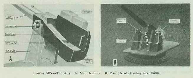
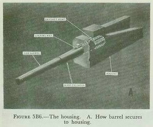
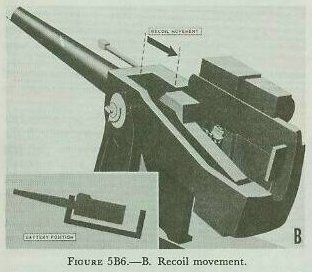
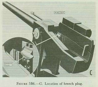
| Now consider these parts in further detail. Figure 5B3 shows how the lower carriage or base ring fits into the stand, and how the mount can move in train. Angle brackets called holding-down clips bolted to the base ring fit under the stand so that the carriage will not tip off the stand when the gun is fired or when the ship pitches and rolls. The base ring can turn on the stand in two large-diameter roller bearings. One takes up vertical thrust; the other, horizontal. The function of the training circle is illustrated in figure 5B3; a pinion in the carriage engages the internal gear of the training circle to train the mount. The carriage assembly is generally considered as two pieces-the lower carriage (base ring) and upper carriage-though on 20-mm mounts the distinction is unimportant. Figure 5B4 highlights these elements. The base ring supports the upper carriage, and the platform or working surface; the shield (in enclosed mounts) is secured to it. It also supports the mount power drives and other components. In mounts equipped with hoists, the hoists are suspended from the base ring and train with the mount. The upper carriage, which in 5-inch mounts may be called the carriage cheeks and in turrets is called the deck lug, is principally the support for the trunnion bearings (figure 5B4). The trunnion bearings and trunnions, in addition to serving as a support which permits the elevating parts to move in elevation, also provide a connection point for air lines (for gas ejection) and mechanical linkages (for mechanical firing linkages and for transmission of elevation movement to firing stop mechanisms). The trunnions are a part of the slide (fig. 5B5), which is conventionally a rectangular steel weldment which houses or supports all the parts of the gun and mount that move in elevation. In modern mounts designed to engage either air or surface targets the limits of elevation movement are from minus 10 to 15 degrees (that is, with gun barrel depressed 10 to 15 degrees below the horizontal) to about plus 85 degrees (that is, with the gun barrel within 5 degrees of pointing straight up, at right angles to the deck). Because of the limitations imposed by turret structure, elevating mechanism, and ammunition feed equipment, turret guns of older design are not capable of these extremes of elevation. Figure 5B5 points up the slide and the elements of elevating gear. The slide contains the ammunition feed mechanism (or the power rammer where ammunition feed is performed manually with mechanical assistance), the recoil brake, the counterrecoil mechanism, the elevating arc, and the gun housing. The function of the elevating arc in positioning the slide in elevation is shown in figure 5B5. The arc is a gear sector secured to the slide. It engages a pinion in the carriage. The pinion may be driven manually or by an elevation power drive. The recoiling parts (that is, those that move to the rear when the gun is fired) of a conventional naval gun are either attached to or are housed in the gun housing (also called the breech housing). The housing and related parts are highlighted in figure 5B6. (Some turret guns and 20-mm guns differ considerably from this type of conventional design, and this description is not intended to apply to them.) Secured to the forward end of the housing is the gun barrel itself. The commonest method of attaching gun to housing is by use of a bayonet joint or interrupted-screw joint, with a key to lock the barrel against possible rotation. The housing can move parallel to the gun bore axis in ways in the slide. It is normally forced to its forward-most position (called battery position) by a counter-recoil mechanism (not illustrated in fig. 5B6), which may be either a powerful coil spring or a pneumatic device. When the gun fires, the reaction of the barrel forces the housing aft; this movement is opposed by the counterrecoil mechanism and by a hydraulic recoil brake (also not illustrated in fig. 5B6.) The counter-recoil and recoil mechanisms will be described and illustrated in a later article of this chapter. Figure 5B6 also indicates the location and some features of the breech mechanism. The type used in most guns of conventional design, including the 5-inch, and illustrated here, is called the vertical sliding-wedge type. Further details of its construction and functioning principles appear later in this chapter. |
 |
 |
 |
 |
 |
 |
 |
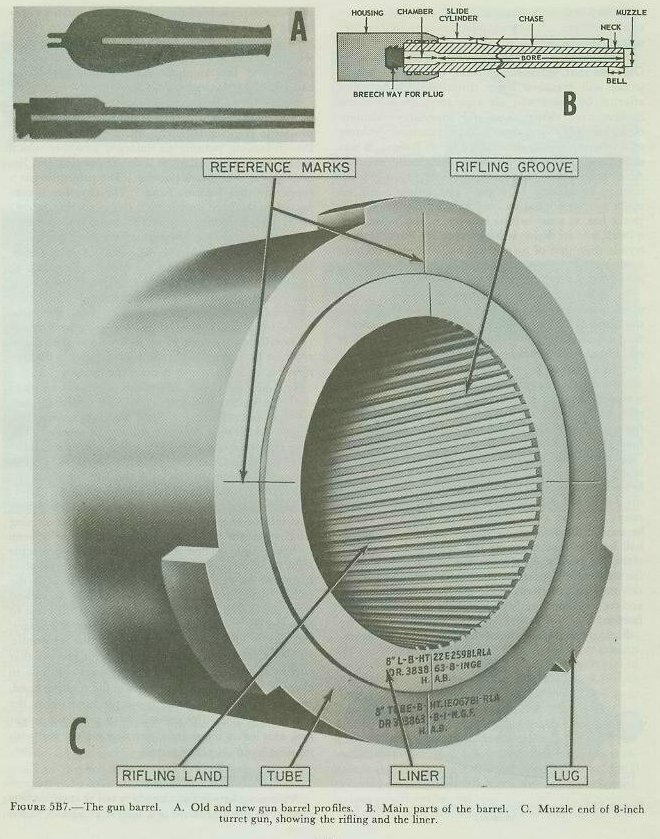
| 5B2. Gun barrel construction Superficially, the modern gun barrel resembles very closely its ancestor of several hundred years ago. The old and the new both are thick-walled metal tubes. The propellant charge and projectile occupy the breech end when the gun is loaded, and the projectile, when fired, issues from the muzzle end. But with this the resemblance ends. Figure 5B7 shows in cross section the old look and the new in gun barrel profiles. The difference in shape is very significant. The figure also points out the main features of the contemporary gun barrel. Let us now consider these more closely. 1. At the breech end is a plug or breechblock which can be opened for loading the gun. Breechblocks take various forms; the illustration shows (as viewed from above) the general structure associated with the sliding-wedge type used in 5-inch mounts. Breechblocks will be discussed in further detail later. Early guns, except for a few custom-made small-arms weapons, were almost invariably muzzle loaders; breech loaders were rarities. Hence the silhouette representing the old gun shows no breech plug. 2. Just forward of the breech plug is an enlarged chamber to contain the propelling charge. 3. The bore is rifled-a set of spiral grooves twists the projectile as it moves toward the muzzle, so that it is spinning when it leaves the gun. Old guns as a rule were smoothbores. In newer types of larger guns, the rifling is cut in a liner-a tubular insert that can be replaced when worn. (Fig. 5B7 shows the rifling cut into the liner of an 8-inch turret gun of recent design. The liner reference marks are used for aligning the liner in the gun tube.) In other guns, the rifling grooves are cut into the barrel. 4. As compared with early guns, the barrel walls are much thinner in modern guns, and the taper is much less exaggerated. As will be explained, improved propellants and improved steels have together brought about this silhouette. Common external features are pointed out in figure 5B7. Many guns have a bell at the muzzle, where the metal is made thicker to discourage any tendency to split. Most modern weapons lack a bell, or instead have lugs, which are utilized when the liner (see No. 3 above) is replaced. (The lugs serve to anchor the tool used for pulling the liner out.) The thinnest part of the barrel, just aft of the bell, is the neck. Then comes the tapering chase, followed by the slide cylinder, which moves in a bearing in the slide during recoil. The after part of the barrel is secured to the gun housing. In the conventional 5-inch gun, the breechblock slides up and down in a grooved rectangular breechway in the housing. Now consider what is between the exterior and the interior surfaces of the barrel-the steel itself. Looking at the profiles of guns old and new (fig. 5B7), it’s evident that although both taper from a wide breech end to a narrower muzzle, the taper is much more drastic in the older weapon. Superficially, this difference in silhouette may seem a small matter, but it is actually very important. It indicates the revolutionary developments in propellants and in metallurgy that differentiate the new from the old. Consider what happens when the propellant in a gun is ignited. As it burns, it turns to hot gas under terrific pressure-up to 60,000 psi in small guns, up to 40,000 psi in larger guns. As the projectile moves along the bore toward the muzzle, the gas pressure goes down. It follows, then, that the chamber wall should be the thickest part of the gun barrel, with the taper from breech to muzzle reflecting the decreasing gas pressure behind the projectile. However, when black powder was the propellant, the chamber had to withstand the initial shock of this propellant’s exceedingly rapid burning rate. Thus, before the projectile was well along the bore, the propelling charge had already developed its maximum pressure as a sudden shock, and the gas pressure was falling rapidly. The breech had to be especially heavy to withstand the shock, but the tube was short because the gas pressure fell so rapidly. In modern guns using pyro or triple-base propellants, the maximum gas pressure is developed far more smoothly, and declines less suddenly. This is reflected to a great extent in the silhouette of the modern barrel. The thinner barrel walls of modern guns are evidence not only of more effective propellants but also of improved metallurgy of the barrel. Before the ‘80’s of the last century, the surest way to make the barrel of a gun withstand more pressure was to make it thicker. But there were limits to this method. Then it was discovered that by prestressing, it was possible to make a gun barrel more resistant to internal pressure. The earliest method of applying this principle was to heat steel ring-shaped jackets, or hoops, to high temperatures, then slip them over the gun tube and allow them to cool. As the hoops cooled, they contracted, until at the end of the process they were squeezing the gun tube inside with a pressure of thousands of pounds per square inch. Guns so constructed are known as built-up guns, and are still made in sizes over 8-inch. About the time of World War I, the same principle was applied to monoblock (one-piece) guns in the radial-expansion or auto frettage process. In this process, a single steel gun tube whose bore is slightly smaller than the caliber desired is filled with hydraulic fluid. The pressure is then built up enough to enlarge the bore permanently about 6 percent. When the pressure is released, the outer layers of the tube tend to return nearly to their original dimensions, while the inner layers, which have been considerably enlarged, tend to maintain their increased diameter. The result is that the inner layers of metal are severely compressed by the contracting force of the outer layers, just as if a hoop or jacket had been shrunk on. In other words, the tube is “self -hooped.” |
 |
| The big advantages of the radial-expansion mono-bloc gun over the built-up type are simplicity of manufacture and comparatively low cost and weight. Because of the difficulty of working on the single huge forgings required for guns over 8-inch, though, larger weapons are still built-up. Or the two methods of prestressing may be combined. |
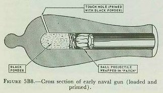
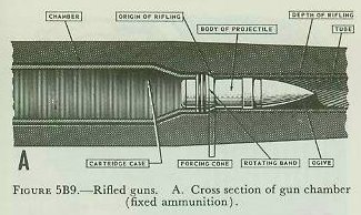
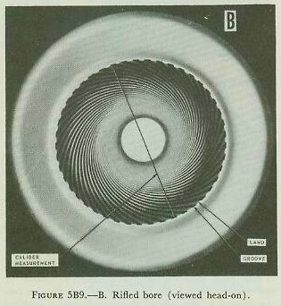
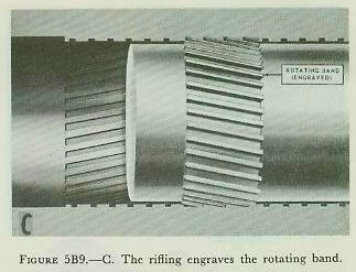
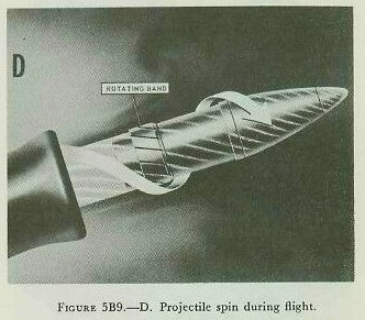
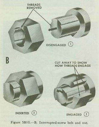
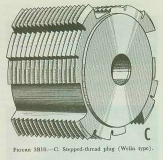
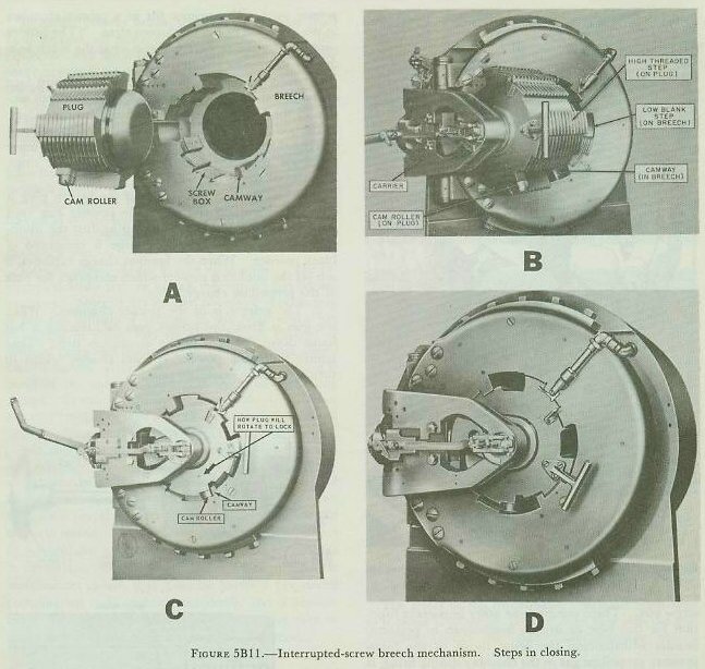
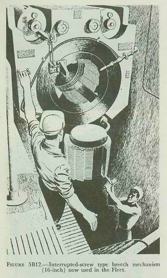
| 5B3. Rifling As the Foreword to this course explains, early guns were capable of hurling a projectile to a respectable range, all things considered. Large cannon could heave an iron or stone ball at a target a couple of miles away, and actually overshoot. But their fire was so inaccurate that a gun capable of an extreme range of about 2,000 yards was considered reasonably certain to hit its target only at point-blank range-in this case, up to 80 or 100 yards. There were several reasons for this poor showing. One was that, other things being equal, a light projectile will travel a lesser distance, and be more affected by wind and air resistance, than a more massive one. Since these old smoothbore cannon could fire only round shot (and the maximum volume of a sphere is rigidly determined by its radius), it was difficult to make the projectile sufficiently massive. An elongated projectile could, of course, be made more massive by making it longer. But unless it can be made to spin around its long axis, an elongated projectile has, as some ballisticians put it, the ballistics of a brick, and its flight path or trajectory is much more erratic than that of a spherical one. Hence, because a smoothbore cannon cannot make its projectile spin, round shot were the only alternative. There were other reasons, too, for the inaccuracy of early gunnery. One standard method for loading the classical type of seagoing muzzle-loading smoothbore required the gunner first to ladle into the breech end of the bore a measured quantity of black powder (later, a paper- of cloth-wrapped “cartridge” was used), and then to ram down the bore the round shot wrapped in a fabric “patch.” Since close clearances would have made loading impossible, the shot was a fairly loose fit. (See figure 5B8.) When the gun was fired (by lighting off a priming mixture which filled a “touch hole” leading into the blind breech end of the bore), the patch was supposed to seal the powder gases behind the loose-fitting ball projectile. But much of the gas would blow by one side or the other. The result was that a lot of the gas pressure was wasted because it didn’t serve to propel the ball, and as the ball left the muzzle it was not likely to be traveling along the bore axis. Hence the ball was slow (300 fps was a likely speed, as compared with 2,700 fps in conventional modem naval medium-caliber guns), and its trajectory predictable only in the most general fashion. Rifling the oldtime muzzle-loading cannon was impracticable because of the difficulty of ramming closefitting ammunition down the length of the bore. Such ramming was possible only in small arms (which is why rifled shoulder weapons were used by infantry as far back as the American Revolution), but not in cannon. Figure 5B9-A illustrates how these problems are solved in modern conventional naval guns. First of all, the projectile is elongated, with an ogival forward end. Breech-loading permits an enlarged chamber which contains more propellant of a slower burning and less erratic type than black powder. The projectile has a copper or alloy rotating band. The chamber is connected to the bore proper by a short tapering forcing cone. When the projectile is rammed into the gun, the rotating band forcibly engages the forcing cone. And the gun bore itself is different. It isn’t smooth. It is grooved or rifled, and the grooving is helical or spiral. (Fig. 5B9-A). The rifling begins at the forcing cone and continues to the muzzle. In all naval guns and small arms except the .45 caliber pistol, the rifling has a right-hand twist. The twist may be uniform (generally around 1 in 15 or 20 times the bore diameter), or increasing (as in the 40-mm gun) so that the twist becomes sharper as it nears the muzzle. The number, depth, and width of grooves varies in different designs. Small arms have relatively few grooves, and cannon (fig. 5B9-B) have a large number. Groove width may decrease toward the muzzle. The bore diameter or caliber of a rifled gun is measured from the top of one land (the high surfaces between grooves) to that on the opposite side of the bore. Since the rotating band for the projectile is slightly larger than the nominal gun bore diameter, the rifling cuts into or engraves the softer metal of the rotating band when the projectile is rammed, as can be seen in figure 5B9-C. When the gun is fired, the projectile spins at an increasing rate as the propellant gas forces it toward the muzzle. (With right-hand twist in the rifling, the direction of spin is clockwise as viewed from the breech.) Moreover, because of the close fit between the rotating band and the rifling it engages, the gas is effectively sealed behind the projectile. (This explains why rifling is made with grooves that narrow toward the muzzle; the grooves continue to engrave wider and wider notches in the rotating band, ensuring a tight fit as the projectile approaches the muzzle.) Figure 5B9-D shows how a projectile might look as it leaves the muzzle, spinning rapidly and with rotating band deeply engraved. 5B4. Breech mechanisms A previous article has already noted that rifling was applied to small arms quite a long time ago. (Rifled small arms were used in the American Revolution, and enabled American sharpshooters to stand at a distance and pick off the redcoats, whose smoothbore muskets were no match for the American rifles either in range or accuracy.) But it could not be applied in a practical way to artillery, either seagoing or ashore. Ramming large-caliber ammunition from the muzzle was excessively difficult if the projectiles fitted the rifled bore closely, and the rifling was useless if they didn’t. The key to making effective and practical rifled cannon lay in the development of effective and practical mechanisms to permit loading from the breech end of the gun rather than the muzzle. With but one exception (which is discussed in volume 3 of this series of textbooks), all naval guns in present use in calibers 40-mm and larger use 1 of 2 general types of breech mechanism. One, which is used in bag guns only, is the Welin interrupted-screw type. The other, used in 40-mm, 3-inch, 5-inch, and 6-inch guns, and in 8-inch turret guns for case ammunition, is the vertical sliding-wedge type. Consider the interrupted-screw type first. Interrupted-screw breech mechanism. The screw is a widely used device for securing something against a heavy thrust. Figure 5B10-A shows how a continuous screw closure might be used to seal the breech end of a metal tube to make a gun of it. Such a breech closure or plug would of course require unscrewing to open the breech after firing. The mass of such a device, designed to withstand the 40,000 psi gas pressure developed in a typical large-caliber cannon, would inevitably be considerable. (The breech plug of a 16-inch naval gun, for example, weighs about 1,400 pounds.) Turning such a screw through several revolutions would not be easy. Application of the principle of the interrupted screw reduces the number of turns required to a fraction of a revolution. If half the threaded area is removed from a bolt (representing the breech plug) and the nut (representing the breech or screw box), then it is possible to insert the bolt (1 and 2 in figure 5B10-B) and engage the two by turning the bolt 90 degrees (3 in figure 5B10-B). The disadvantage of this straightforward application of the interrupted-screw principle is that half the threaded area must be removed, and this reduces the “holding power” by reducing the amount of thread area that can be engaged. This disadvantage is partly obviated by the Welin stepped-thread breech mechanism. In this arrangement, both plug and breech have steps. The steps are arranged in groups, with each group of four ascending (or descending) steps occupying one 90 degree sector. On the plug (figure 5B10-C), the lowest step of each group is blank, and the others are threaded. On the breech screw box the highest step in each group is blank, and the others threaded. Figure 5B11 shows how an obsolete 14-inch breech mechanism functions in closing. The principle is the same on present-day 8-inch and 16-inch bag guns now in the Fleet, but in those ships the plug swings in a vertical arc (as in figure 5B12) rather than a horizontal one. Note that there are two distinct motions of the plug in opening and closing-a translating movement in which the plug swings on a massive carrier hinged to the side of the breech, and a rotating motion in which the plug screws into the screw box. Both of these may occur together in the final stages of closing or the beginning of opening. Now follow the breech-closing action as illustrated in figure 5B11: 1. From its open position, the plug swings around toward the screw box. As the plug moves in, each high threaded step of the plug fits into a low blank step of the screw box (fig. 5B11-B). The high threaded steps on the screw box fit into the low blank sectors of the plug. The other threaded steps also clear each other in this position. 2. When the plug is well into the screw box, but has not yet begun to rotate, a cam roller on the plug contacts a camway in the screw box. (Figure 5B11-C shows how the plug must rotate to engage the screw box.) 3. During the last part of its translation into the screw box, the plug’s cam roller engages the camway and the plug turns so that the mating threads on box and plug engage. Figure 5B11-D shows the breech closed, locked, and ready for firing. |
 |
 |
 |
 |
 |
 |
 |
 |
 |
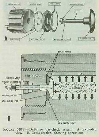
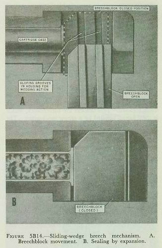
| Notice the two great advantages of the Welin-type screw box and plug: 1. About 75 percent of the engaging surfaces of plug and screw box are threaded. 2. The plug requires only about 27.5 degrees of rotation for full engagement and locking. Compare these characteristics with the original bolt and nut, and you can see the improvement. Welin-type breech mechanisms may have 3, 4, or even 5 steps, counting the blank sectors. In most modern installations, the plug swings vertically up into the screw box (fig. 5B12) rather than horizontally as in the 14-inch breech pictured in figure 5B11. Because of the large size of the guns on which they are generally found, interrupted-screw plugs are too heavy for unassisted operation by hand. (As noted above, on a 16-inch gun the plug may weigh as much as 1,400 pounds.) Interrupted-screw mechanisms for these large guns are therefore generally fitted with air- or spring-powered devices to aid the gun crew in operating them. These devices will be discussed further in chapter 7 on turrets. The discussion of the interrupted-screw type breech mechanism so far has concentrated on the principles of operation of the engaging parts-the plug and screw box. There remains one other important function for this type of breech mechanism to perform. Besides withstanding the brute thrust of the high-pressure propellent gas in the chamber during firing, it must also prevent leakage of the burning, toxic gas into the turret or mount. It does this by means of an obturator or sealing device-the DeBange gas-check system. The DeBange gas-check system is used in all United States Navy bag guns. Its main parts are the mushroom, gas check pad, split rings, and gas check seat. Figure 5B13 shows a typical gas-check assembly. The biggest component is the mushroom. (In a 16-inch gun it weighs 220 pounds.) It consists of a large flat steel head at the forward face of the plug, with a long steel stem extending through a hole in the plug and protruding from its rear face. Through the center of the stem and head passes a hole called the primer vent. The primer fits in a primer chamber in the after end of the mushroom stem. (The primer vent does for the modern bag gun what the touch hole did for its ancient counterpart.) Between the mushroom head and the forward face of the breech plug, and bearing against a smooth section of the breech chamber called the gas-check seat, is the gas-check pad. This is a thick flat resilient doughnut-shaped disc of plastic, whose outer and inner edges are protected from wear by steel split rings. The system works this way: 1. When the gun is loaded and the breech plug is closed, the ignition charge in the powder bag (not shown in figure 5B13) is right up against the mushroom head. (The ignition charge is composed of black powder. When the ignition charge explodes, it sets off the smokeless powder which comprises the bulk of the propelling charge.) 2. The primer is in the primer chamber. When the gun is fired, the primer goes off, sending a hot flame down the vent in the mushroom stem. That ignites the black powder ignition charge, which in turn sets off the smokeless powder. 3. As the powder burns, the expanding gases push hard against all sides of the breech chamber, the projectile, and the mushroom head. The only thing that can yield is the projectile, which begins to move up the gun bore. Meantime the pressure goes higher and higher up to 40,000 psi until the projectile is fully under way, when the pressure tapers off. 4. As the pressure increases, it shoves the mushroom head hard back against the gas-check pad. The pad expands against the gas-check seat, effectively sealing the breech against the escape of gas. And note this feature of the device-the greater the gas pressure, the harder the mushroom compresses the pad against the gas-check seat. Vertical sliding-wedge breech mechanism. The interrupted-screw type of breech mechanism has its advantages. Since it has its own obturator mechanism, it can use propelling charges in silk bags which are consumed in firing, and once the bore is cleared of residual gases and burning fragments, the next round can be loaded without requiring extraction and disposal of the used container for the fired propelling charge. It can also be used (though the U. S. Navy has no guns of this type in active service at the present time) to fire case ammunition. But this kind of breech mechanism also has disadvantages. One is really to be ascribed particularly to the nature of the ammunition itself. Because of the fire hazard, a crewman must inspect the chamber after each round fired to ensure that it is safe to load the next round. This slows the rate of firing. More important, this kind of breech mechanism is complex in operation. Coupled with the number of separate ammunition details that must be handled per round (totaling up to 8-primer, projectile, and 6 powder bags), this type of breech mechanism is not easy to adapt to automatic or semiautomatic operation. For this reason, guns 40-mm and up, of late designs, use a breech mechanism that works on a completely different principle-the sliding-wedge breech mechanism. This uses a sliding element to block off the breech opening. The sliding breechblock may move either horizontally or vertically. Figure 5B14 shows in simplified form the elements of a vertical sliding-wedge breech mechanism as it looks from the side, with the breechblock or plug in its lowered (open) position. The dotted outline represents the breechblock in its raised (closed) position. Notice that the grooves in which the plug can slide up and down are not exactly vertical; they’re slanted slightly forward. It is clear that in its open position the plug is noticeably aft of its closed position. Or, in other words, in rising to the closed position, the breech-block moves forward as well as upward. The effect of the breechblock’s forward movement as it closes is to wedge the cartridge case into the gun chamber (hence the name sliding-wedge breech mechanism). |
 |
 |
 |
 |
 |
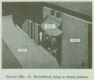
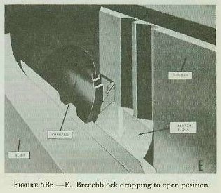
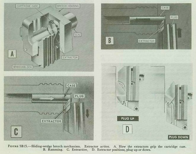
| The method of obturation used in this type of breech mechanism depends on the cartridge case for sealing effect. There is no sealing device incorporated into the breech mechanism. Figure 5B14 shows what happens when the gun fires. As the propelling charge burns, the hot powder gases expand against the sides of the cartridge, which in turn expand against the smooth walls of the chamber and against the breech-block. Since the cartridge case tightly seals off the entire length of the chamber, the gases can escape only forward, driving the projectile. None can escape through the breech. This is sealing by expansion. But after the gun fires, the chamber is not clear. The cartridge case is not designed to disappear with the burning propelling charge, and it must be removed from the chamber before a new round can be loaded. Therefore all guns with sliding-wedge breechblocks have one or a pair of extractors as part of the breech mechanism. In 40-mm, 3-inch, and 5-inch guns the extractors are mechanically operated by breechblock movement. Figure 5B15 shows several views to clarify their functioning. When the breechblock is down (open) the extractors are pulled back. In these guns the extractors perform the dual function of locking the breechblock down and extracting the case. As a fresh round of ammunition is rammed into the chamber, the rim of the cartridge case engages the extractors, and pulls them forward. This unlocks the breechblock, which is then forced upward by a spring mechanism. The round is chambered, the breechblock moves upward, and the extractor tips move forward in a coordinated group of movements. When the breechblock is fully closed, it has forced the round fully into the chamber, and the extractor tips have seated in recesses in the housing. (Figure 5B6 shows those recesses). After the gun fires, the breechblock is opened by camming action. (The details of this action vary in different gun designs, and will be described in subsequent chapters.) As the block drops, the extractors retract. They haul the fired cartridge case out of the chamber and catapult it to the rear into the slide. At the extreme of their rearward movement, they lock the breechblock down until the next cartridge case again pulls them forward to unlock the breechblock. Figure 5B15 shows the type of breech mechanism used in conventional 3-inch and 5-inch guns. In 40-mm guns the sequence of operations is similar, but the extractors are pivoted on a spindle, and lock the breechblock down with a pair of hooks. In 3-inch and 5-inch breech mechanisms the extractors are not pivoted, but rock back and forth on their forward curved surfaces, which bear against the gun housing. The movement of each extractor is controlled by two lugs; the inner lug engages a camming groove in the breech-block, and the outer one oscillates in a small curved groove in the housing. It is also noteworthy that in 3”/50 guns equipped with power loaders the breech-block-locking function of the extractors merely supplements the normal functioning of another locking mechanism (described in another chapter). But, regardless of the method of locking, the extractors unlock the breechblock when they are moved forward by the cartridge case being loaded. In contrast to the sliding-wedge breech mechanisms described above, which are operated through mechanical camming and spring action when the gun housing moves backward and forward in recoil and counter-coil, the breech-mechanism in 6-inch and 8-inch case guns are operated hydraulically. The descriptions above do not apply to the very newest designs of 3-inch and 5-inch gun mechanisms with sliding-wedge type breech mechanisms. See volume 3. Bolt-type breech mechanisms. The sliding-wedge and interrupted-screw types of breech mechanisms are not used in guns 20-mm and smaller. These use variants of the bolt principle. The bolt is a breech-block which moves in line with the bore axis-forward to close the breech, and to the rear to open it. In so-called bolt-action weapons like the old M1903 rifle (the famous “Springfield” of World War I) the bolt is operated by hand. In gas-operated weapons like the Browning automatic rifle M1918A2 (the “BAR”) or the Ml rifle (“Garand”) the bolt is cammed to the rear by a piston actuated by a small amount of propellent gas diverted from the barrel while the bullet is moving through the bore. Spring action forces the bolt forward to rain the next round home. In recoil-operated weapons like the Browning machine guns, a complex of mechanical parts is forced to the rear to varying distances by recoil, and is then driven forward by springs to reload and fire the next round. In blowback-operated weapons like the 20-mm AA gun and the Thompson or M3 submachine guns (“Tommy” guns) the bolt is pushed back, when the gun is fired, by gas pressure in the chamber, and a spring mechanism afterward forces it forward to ram the next round home. Aircraft machine gun designs use all three of these actuating forces (gas, recoil, and blowback). |
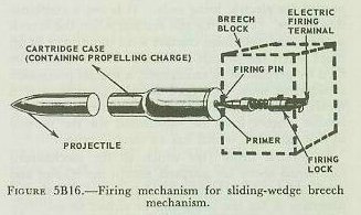
| 5B5. Percussion and electrical firing systems An earlier chapter, on ammunition, describes the types of primers that are used in gun ammunition to initiate the propelling charge. With regard to functioning, it distinguished between percussion, electric, and combination primers. It also described a special type of primer used in bag ammunition. (The other types are all associated with case ammunition.) Firing mechanism for case guns. The commonest ammunition, and the commonest guns, are of the case type, and it is appropriate to look at these first. Figure 5B16 shows the principal common element of a percussion or combination firing system. Of course, not all the elements of a percussion or combination firing system are common to all gun designs. Since this chapter is concerned primarily with common elements, other important parts that are not common are omitted. The important common element is the firing mechanism, sometimes called the firing lock. This part is secured in the breechblock, but is not considered part of the breechblock, and is very easily removed for cleaning. The illustration shows a combination electric-percussion firing mechanism typical of case guns 3-inch and larger. Mechanical linkage in the breechblock operates the firing mechanism in the following ways: 1. It retracts the firing pin or striker when the breechblock is not fully closed. 2. It cocks and releases the firing pin or striker to fire the cartridge case by percussion. The part in the breech mechanism that does this is called the sear. (Not illustrated in figure 5B16.) In different gun designs this function is accomplished in different ways: a. In the conventional 5-inch gun, for example, the firing pin or striker moves into contact with the primer in the cartridge case as soon as the breech closes fully, and remains in contact until the breechblock begins to drop. In percussion fire, a massive spring-loaded part in the firing mechanism is released by the sear in the breechblock to strike a bushing, through which the impact is delivered to the firing pin and thus to the primer. b. In 3”/50 guns, the firing pin contacts the primer as soon as the breech is closed, and remains in contact unless the percussion firing linkage is actuated. When this happens, the sear (which looks and works differently from its namesake in the 5-inch gun) retracts the spring-loaded firing pin and releases it to strike the primer. c. In 40-mm guns the firing pin automatically strikes the primer as soon as the breech is fully closed. Firing is controlled by regulating rammer action, as described in a later chapter. The 40-mm firing mechanism is a percussion-only device. d. In 6-inch case guns the firing mechanism closely resembles the conventional 5-inch firing mechanism briefly discussed above. In 8-inch case guns, however, the firing mechanism is stripped to the essentials needed for electric firing only. It is not a combination device. The firing pin retracts when the breech is open, and maintains contact with the primer at all times when the breech is closed. When it must be fired by percussion in emergency, a special percussion attachment must be rigged for the purpose, and a special type of cartridge case equipment with percussion primer must be substituted for the normal service cartridge, which has an electric primer. |
 |
 |
 |
 |
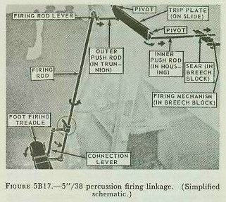
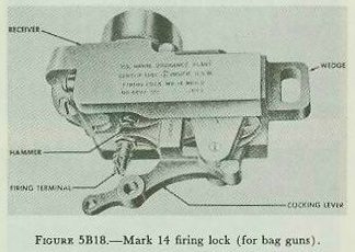
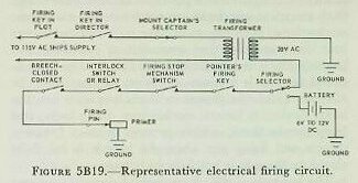
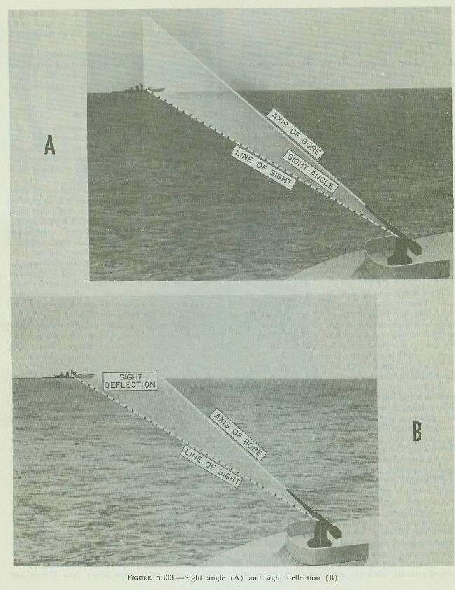
| In electric firing (for which all the mechanisms mentioned above are adapted, except the 40-mm and some older 3-inch hand-loaded mounts), all that is necessary is for the firing pin or striker to maintain good electrical contact with the case primer. When the firing circuit is closed, current passes through the cable and the firing pin through the primer’s contact and filament, then by way of the cartridge case and gun to ground. The breech mechanism device which retracts the firing pin automatically prevents firing both by percussion and electrically when the breech is not fully closed. Percussion firing linkage (for case guns). Mounts (40-mm and larger) in which percussion firing is considered an alternate rather than an emergency method of fire, conventionally have foot pedals at the pointer’s station for control of percussion fire. In 40-mm mounts, depressing the pedal part way causes an electrically driven firing linkage to release the rammer and initiate firing. If the electrically driven linkage is not functioning, depressing the pedal all the way initiates firing mechanically. In either case, the actual firing in the gun is done by percussion. In 3-inch mounts of the older hand-loaded type, “electric” firing is an alternate method, but here, too, so-called “electric” firing is done by percussion; the percussion firing mechanism is actuated by a solenoid. “Percussion” firing is done by depressing the foot pedal; this operates the firing linkage directly. In newer 3”/50 mounts with automatic loading equipment, percussion firing is an emergency expedient, and must be done by operating a control on the slide. Figure 5B17 shows in simplified form the firing linkage for a conventional 5”/38 mount. Any percussion firing linkage from a foot pedal to the slide or breech-block uses similar mechanical elements. The little arrows show how each part of the linkage moves when the pointer steps on the treadle. The treadle tilts down, swinging the rectangular connection lever assembly aft, and so rotating the firing rod. A firing rod lever at the top of the firing rod pushes the outer push rod, which runs inboard through the inner surface of the slide. The trip plate transmits the push to the inner push rod in the housing. If the breechblock is fully closed, the inner push rod accomplishes the entire purpose of this linkage, which is to push the sear to the right. (It will be recalled that the sear releases the cocked firing mechanism.) Note two important safety features of this linkage: 1. The trip plate can push the inner push rod only when the gun is completely in battery. 2. The inner push rod can push the sear only when the breechblock is fully closed. In 6-inch case-type turret guns percussion firing is an alternate method, and the general operation resembles that in conventional 5-inch mounts. In 8-inch case-type turret guns percussion firing is an emergency method. As an earlier paragraph in this article has pointed out, it requires attachment of a special percussion firing accessory and use of a special cartridge. Bag-type firing lock. In bag guns the primer is in a small cylindrical case loaded separately from the remainder of the round into a primer chamber. When the gun fires, the spit of flame from the primer passes through the primer vent in the mushroom stem of the DeBange mechanism and ignites the ignition charge on the after end of the rearmost powder bag. This general arrangement is illustrated in figure 5B13. The primer chamber is in the mushroom stem, and the firing operation is carried out with a firing lock which by means of an interrupted-screw joint fits onto the after end of the mushroom stem. The firing lock in general performs the same function as the firing mechanism in a sliding-wedge breechblock. All bag guns now in active use in the Fleet use the same firing lock, the Mark 14. (See figure 5B18.) It is described in further detail in the chapter on turrets. It has a little sliding-wedge type breech mechanism, which is mechanically linked to the gun’s breech plug so that it normally closes and opens with the plug. It cannot fire the primer unless the plug is closed and locked. However, it can be opened while the plug is locked so that a defective or misfired primer can be replaced. For electric firing, the firing lock has a terminal to which a lead from the electrical firing circuit can be attached. The firing pin in the lock is kept in contact with the bag combination primer when the lock is fully closed, to permit electric firing. For percussion firing a lanyard is connected to the cocking lever on the lock; pulling steadily back on the lanyard first cocks and then releases a hammer which strikes the firing pin. Electric firing systems. So far, the discussion here of electrical firing has dealt with electric or combination primers, and with the firing mechanism proper- which has as electrical elements only an insulated firing pin and a quick-disconnect terminal to which a firing lead or cable is attached. But this is only the final part of the electrical firing system. Figure 5B19 shows schematically the elements that will be found in a typical electrical firing system for a mount or turret. The diagram does not show scalar distances or the physical locations or appearance of the elements. Firing under normal service conditions is performed using the ship’s 115-V ac-c supply as a current source. Trace the circuit beginning with this source. There are switches (not shown on the schematic) in fire-control plot which determine where control of automatic fire will be placed, and at least one firing key on the stable element or stable vertical in plot. (The key is a spring-loaded normally open switch which may be mechanically latched in closed position.) There is a firing key in the director, and, in some mounts (like the 3”/50 with automatic loader), a selector at the mount captain’s station for cutting one or both guns of a twin mount in or out of the circuit. All these are in the 115-V line to the primary of the firing transformer located at the mount. The firing transformer’s secondary feeds 20-V a-c to a firing selector switch (sometimes called a firing snap switch). This switch, generally at the pointer’s or mount captain’s station (depending on the mount concerned), permits selection of a-c from the transformer or d-c from a local battery. In many mounts, the a-c position is labeled MOTOR GENERATOR and the d-c position is labeled BATTERY. The normal position, which is used if firing is to be controlled remotely by plot or by the director, selects the transformer. The battery supplies firing current in emergency, and can also supply emergency current for lamps illuminating the sight setter’s scales and the sight telescope reticles. (The lamps normally get their current from an illumination transformer, not shown in figure 5B19.) After the firing selector switch come a number of switches or contacts on the mount. The pointer’s firing key is generally on one of the elevating handwheels, and is connected to the circuit by a flexible cable. The firing stop mechanism switch is part of the firing stop mechanism (to be described later). It opens the firing circuit when the gun is pointed where it will endanger part of the ship’s structure. Some mounts have no interlock switch or relay, but such interlocks are a common feature of mounts with automatic loading equipment or hydraulically operated breech mechanisms. The one shown in the schematic may represent up to six or more, each of which registers that a certain mechanism or part is in a position that is safe for firing. Such electrical interlocks are not limited to automatic mechanisms; even bag guns have such devices to register, for example, that ammunition handling and loading gear is in safe position for firing. The breech-closed contact is a common variety of interlock. In addition (and not shown in the schematic) are the safety devices in breech mechanisms, firing locks, and firing mechanisms, which prevent contact between primer and firing pin when the breech is not fully closed or the gun is not fully in battery. The last part of the circuit is the firing pin’s contact to the electric primer. The circuit is completed through the filament in the primer, the cartridge case, and ground return to the firing transformer or battery. Note the emphasis on safety in this circuitry. All the switches and keys are in series. Any link in the circuit can break the entire circuit if conditions are unsafe at that point. Yet the mount is capable of firing under local control if the remote system has failed. Firing stop mechanism. At any greater range than point-blank (a range so small that the gun need not be elevated above the line of sight to the target) a gun when correctly laid is aligned with a point other than the target. The greater the range, the greater the deviation. This makes it possible, particularly in enclosed mounts, for a pointer or trainer, looking through a telescope, to see no obstacle in the line of sight, while the gun’s bore may be in line with some part of the ship’s structure, so that firing the gun will damage the ship. For this reason measures are taken either to prevent the gun bore from being brought into alignment with the ship’s structure, or to prevent it from firing under these conditions. The former method is used on some 20-mm AA mounts, where a large circular cam surrounding the stand prevents depression of the gun barrel below safe limits. And on some carriers there is provision for preventing 5-inch mount power drives from positioning the gun so that its bore axis will be aligned with the ship’s structure. But by far the commonest device for preventing this kind of accident is the firing stop mechanism, which disables the firing system when the gun is aimed on a bearing or elevation that endangers the ship on which it is mounted. |
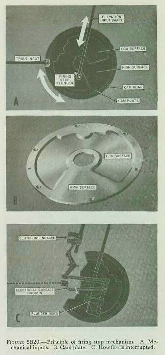
| Figure 5B20 shows the fundamental mechanism used in all mounts larger than 20-mm. It is essentially a disc-type cam, in which the inputs are gun train (which rotates the cam) and gun elevation (which moves the cam follower approximately radially across the cam). A spur gear driven by the mount training gear engages the radial gear teeth around the circumference of the cam plate or disc. The elevation input shaft moves toward the center of the cam plate when the gun elevates, and toward the edge of the cam plate when it depresses. At the end of the elevation input shaft is a spring-loaded plunger which maintains contact with the cam plate. When the gun mount is installed, the axis of its bore is observed through all angles of train and elevation. Each position of the gun (as defined by its train and elevation) corresponds to a location of the plunger on the cam plate. The angles of elevation and train at which the gun endangers parts of the ship’s structure are plotted on a special diagram that corresponds to the cam area. Then the cam plate surface is machined. The surface is cut so that safe areas are depressed, while danger areas remain the original surface of the plate. Thus, when the gun is positioned at angles of train and elevation where it is safe to fire, the plunger rides on the depressed surface of the cam plate. As soon as the gun trains or elevates to a bearing or elevation which aligns the bore with any part of the ship’s structure, the plunger rides on the uncut surface of the cam plate. Plunger movement, as the plunger rides up to the uncut surface or down to the depressed surface of the cam, is communicated by a mechanical linkage to a clutch and to a switch. As figure 5B20 shows, the clutch is in the mechanical linkage of the percussion firing system. (The clutch is also shown (encircled) in figure 5B17.) The switch is in the electrical firing circuit. When the plunger is riding on a high (danger) cam plate area, the clutch is disengaged, interrupting percussion fire, and the switch is opened, interrupting electrical fire. When the plunger is riding on a low (safe) cam plate area, the clutch is engaged and the switch is closed, permitting fire. Firing stop mechanism functioning is completely automatic. It requires no attention from the gun crew after installation, beyond periodic maintenance checking to see that it is functioning properly and requires no adjustment. Only if the mount location or ship’s structure is changed is it necessary to revise the cam plate. In this case, the cam plate is replaced by one cut to a new pattern. Firing stop mechanisms on turrets function only to interrupt the electrical firing circuit. (There is, obviously, no way to interrupt the percussion firing linkage, since the only connection between the firing lock and the individual firing the gun by percussion is a lanyard.) Therefore an indicator lamp for each gun shows whether or not the gun is positioned on a safe bearing and elevation. |
| 5B6. Recoil and counterrecoil systems. Novels about life aboard naval vessels of a hundred years ago or more, frequently have at least one scene in which a naval gun mount breaks loose-either in battle, during a storm, or both-and thunders, an uncontrollable Juggernaut, across the deck as the ship rolls in heavy seas. This is something that can scarcely happen aboard a modern naval vessel; other gear may break loose, but it is hard to see how a gun mount can. Why were not the guns in the days of sailing vessels simply secured to a fixed mounting, as guns are today? The answer is that modern guns have recoil and counterrecoil mechanisms, and ancient guns did not. A naval gun can be rigidly secured to the deck, but without some provision for its recoil it will break loose when fired. Recoil is simply the manifestation of the third of Newton’s three laws of motion-the one that says, with deceptive brevity: “To every action there must be an equal and opposite reaction.” The enormous thrust that can send a ton of steel screaming at supersonic speed toward a target over 20 miles away acts not only on the projectile, but on the gun. Yet, though the recoil of a full broadside salvo on a BB will push it sideways like a piece of driftwood, the guns themselves do not break loose and roll threateningly across the deck. Why? The answer, again, is that these guns have recoil and counterrecoil mechanisms. The antique naval gun was fired from “battery” position-with the mount pushed as far outboard through the gun port as the bulkhead would permit. Its recoil hurled it inboard, rolling on its wheels until it brought up against its stout tackle. In this “recoil” position, well back of the gun port, the bore could be swabbed, and the powder and ball loaded for the next shot. Then the crew hauled it up to battery position, and lit off the primer to fire again. Thus in naval guns the entire gun carriage, or what we would now call the mount, was rolled backward in recoil and forward (manually) in counterrecoil. Artillery ashore did this too; the classic example (1904) is the Russian gunners fighting up a hill at Port Arthur-firing, then chasing madly down the hill after their runaway pieces, and laboriously hauling them up the hill again (if they could get them up) for the next round. As naval gun mounts evolved, control over recoil improved. Engravings of the interior of post-Civil War monitors (early descendants of the Union’s pioneer armored and turret-equipped war vessel) show tracks on which the great guns recoiled when fired. But it wasn’t until shortly before World War I that effective recoil brakes and counterrecoil mechanisms were developed. These were, for the time, triumphs of metalworking accuracy and engineering ingenuity, and were treated as military secrets, much as a new type of radar application or atomic bomb trigger mechanism is treated today. |
 |
 |
 |
 |
 |
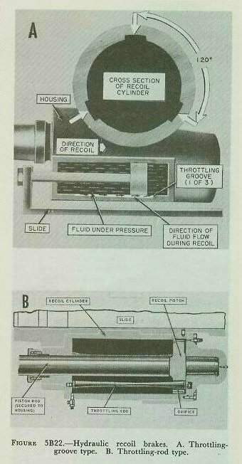
| There are a number of different types of recoil brakes and counterrecoil mechanisms that have been found efficient in land artillery and elsewhere, but the United States Navy uses in naval gun mounts but 1 general type of recoil brake (in either of 2 variants) and but 2 kinds of counterrecoil mechanism. But before considering these, note the general functions of these devices: 1. A recoil brake is primarily designed to absorb the force of recoil and “spread” it so that the sudden heavy shock is converted to a thrust exerted over an appreciable distance through which the recoiling parts of the gun are permitted to move. In the mechanical sense, work is done by the recoil force in pushing the gun and housing aft against the resistance of the recoil brake; the energy absorbed in the brake appears as heat. a. A secondary function of all recoil brakes in naval gun mounts is to bring to a smooth stop by dash-pot action the forward movement (counterrecoil) that follows recoil. 2. A counterrecoil mechanism is a device that stores some of the energy of recoil and uses it to force the recoiling parts forward into battery after the projectile has left the gun muzzle. (The energy of recoil can, of course, be traced ultimately to the combustion of the propellant.) Recoil and counterrecoil mechanisms are designed to work together. Figure 5B21 shows in a general way where the recoil and counterrecoil systems are located in a conventional 5-inch mount. Recoil systems. All present-day recoil systems for naval guns larger than 20-mm use hydraulic recoil brakes. A hydraulic recoil brake is a mechanism of the type commonly termed by engineers a “dashpot.” It has a piston and a cylinder which can move with respect one to the other. There is a liquid in the cylinder which can move from one side of the piston to the other, but its rate of movement is restricted or “throttled.” The two general variants of this type of device are shown in figure 5B22. In one variant (A in the figure), the piston is solid, and each cylinder is filled with recoil fluid (usually a mixture of water with glycerin). In the wall or liner of each cylinder are cut three throttling grooves 120 degrees apart. They are shallow at the forward end of the cylinder and deepen toward the after end. When the gun is fired, the force of recoil pushes the housing and the recoil cylinders within it to the rear, thus exerting pressure on the fluid in the forward end of the cylinder. But the throttling grooves permit the fluid to flow around the piston at a reduced or throttled rate. The cylinder can, therefore, yield to recoil thrust and move aft, subject to the continuous braking action of the hydraulic fluid as it flows through the grooves from the forward end of the cylinder to the rear. Since the recoil fluid can flow only at a rate proportional to the size of the throttling grooves, the recoil brake resists the force of recoil over its entire stroke. In effect the recoil brake, by distributing the force of recoil over the length of the recoil stroke, converts this force from a sudden, destructive impact to a still-powerful, but controllable, thrust exerted over a considerable distance. Note that the grooves are TAPERED. (In the figure, in order to show this more clearly, both the taper and the size of the groove are exaggerated.) At the beginning of the stroke the grooves are comparatively deep, so that the fluid will not offer too much resistance to the initial thrust of recoil. As the housing moves aft, the grooves become shallower, until by the end of the recoil stroke the grooves are very shallow indeed. By this time the force of recoil is spent, and, by throttling the fluid flow down, the shallow grooves help to bring the housing to a smooth stop. In the conventional 5-inch gun there are two recoil cylinders of this kind, symmetrically arranged about the long axis of the housing. Since the cylinders are bores in the housing, in this design the cylinders move in recoil while the pistons are fixed to the slide by the piston rods. A transverse bore in the housing, called the equalizer hole, permits enough fluid flow between cylinders to equalize the pressures built up and the resistance offered by the two cylinders to recoil movement. In other designs, there may be but 1 recoil cylinder, or 2 cylinders may be arranged asymmetrically. Or the recoil cylinder may be in the slide, while the recoil piston rod is secured to the housing. All of these variations on this type of recoil brake can be found in United States naval gun mounts. The other major variant in recoil brakes is in guns 6-inch and larger. This kind of recoil brake has a somewhat different method of controlling recoil fluid flow. Instead of being solid, the piston has 3 holes bored in it, spaced 120 degrees apart. Through each of the holes passes a tapered throttling rod secured to the ends of the recoil cylinder so that it is parallel to the piston rod. (For simplicity’s sake, only one throttling rod and hole are shown in figure 5B22.) There are no throttling grooves. As the piston moves in recoil, the fluid that it displaces can flow from one end of the cylinder to the other only through the holes. Because the throttling rod varies in diameter at different points, it blocks off a varying portion of the hole as the piston moves in its stroke. Where the rod’s diameter is large, for instance, it blocks off most of the hole, leaving only a small opening for fluid flow, and the braking effect is large. Where the rod is small, on the other hand, less of the opening is blocked, and more fluid can pass, with decreased braking effect. The rods are so tapered as to provide evenly distributed resistance to recoil thrust over the length of the recoil stroke. One advantage in the use of throttling rods is that the rods can be replaced with others of different taper if a change in the gun’s recoil characteristics is desired. All recoil systems used in United States naval guns incorporate a counterrecoil buffer dashpot mechanism used in bringing counterrecoiling parts to a smooth stop. This is discussed further in connection with counterrecoil systems. |
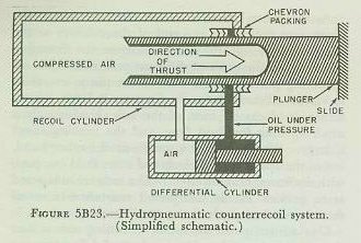
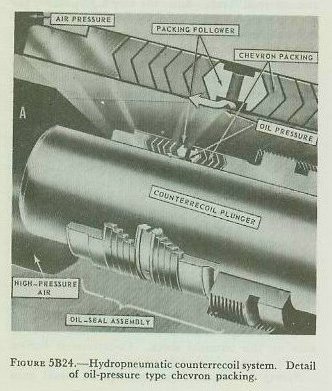
| Counterrecoil systems. There are 2 basic types of counterrecoil systems (also called recuperator) used in United States naval guns. Guns smaller than 5-inch use 1 or more counterrecoil springs. (These are sometimes termed recoil springs in OP’s and elsewhere, but the function is the same.) Guns 5-inch and larger use pneumatic recuperators, which depend on compressed gas (generally air or nitrogen) to provide counterrecoil thrust. Since the very high-pressure gas used in such systems is sealed by use of packings under hydraulic pressure, such systems are most often called hydro pneumatic counterrecoil systems. The functions of any counterrecoil system are primarily to return the recoiling parts of the gun to battery after the recoil stroke, and secondarily to hold the recoiling parts in battery. Thus a counterrecoil system must not only provide thrust to return the recoiling parts to battery, but must also develop enough continuous thrust at all times to hold them there except while the projectile is actually being propelled through the bore. This is in contrast with recoil brakes, which develop their “reverse thrust” for braking only while the recoiling parts are actually moving in recoil, and at other times exert no forces on the gun parts. Because it continues to develop a heavy forward thrust “following through” to the end of the counter-recoil stroke, any counterrecoil system tends to drive the recoiling parts into battery with considerable shock. For this reason, all counterrecoil systems for guns with massive recoiling parts (which include guns 40-mm and up) must have a counterrecoil buffer to take up this terminal shock. Counterrecoil buffers are discussed in further detail below. Spring counterrecoil systems. In all naval guns smaller than 5-inch, coil springs provide counterrecoil thrust. In late 3”/50 mounts and most 40-mm mounts, the springs surround the exterior of the barrel (water jacket in 40-mm mounts). In single Army-type 40-mm mounts and in some earlier marks of 3”/50 hand-loaded mounts the springs are concealed; in some 3-inch mounts they may be the recoil cylinder. Hydropneumatic counterrecoil systems. Figure 5B23 shows in simplified form how a pneumatic counterrecoil system works. It requires a cylinder or bore (in the housing) charged with gas (generally nitrogen or air, never oxygen or other chemically active gas). Gas pressure in a conventional 5-inch system (which is typical) is around 1,500 psi. A plunger fitting into the after end of the housing is forced outward (to the rear) by the gas pressure against the after end of the slide. The thrust exerted by the plunger against the slide holds the housing in battery and returns it to battery after firing. The complication of this arrangement lies in the packing which surrounds the plunger in the housing. Ordinary packing, unsupported, will not withstand the gas pressure in the counterrecoil chamber. Therefore the packing used is a chevron type “inflated” by oil under pressure. (Figure 5B24.) The oil pressure in the packing is always higher than that of the gas in the cylinder. Figure 5B25 shows functionally the device that ensures this pressure relationship-the differential cylinder. One end of the differential cylinder (to the left in figure 5B25) is connected to the air chamber. The other (right end in figure 5B25) is connected to the oil-charged packing, and is full of oil. The piston is free-floating, and the piston rod on the oil side goes through a packing gland to the outside, but does not connect mechanically to any other component. The values for dimensions and pressures shown in the figure and in the discussion below are not intended to represent any specific installation, but serve only to illustrate the principle of the differential cylinder. Suppose the total area of either face of the piston is 3 square inches, but the cross-section area of the piston rod is 1 square inch. The air pressure of 1,500 psi is exerted on the full piston area of 3 square inches, and the total thrust or force developed is 3 x 1,500 or 4,500 lbs. But on the other side of the piston only 2 square inches are exposed to oil pressure, since 1 square inch is occupied by the piston rod. (For the sake of simplicity, atmospheric pressure on the outside end of the rod is neglected in this example.) The oil is therefore subjected to a thrust of 4,500 lbs. exerted on a 2-square inch area. Hence it is under a pressure of 2,250 psi, which is higher than that of the air (1,500 psi). The pressure is communicated to the packing. It is obvious that even though the air pressure fluctuates, the pressure relationship will remain the same (in the ratio, oil to air, of 3:2), so that the packing will always be under higher pressure than the air. The differential cylinder serves not only as a device to maintain pressure in the packing, but also as an indicator of oil level in the sealing system. When the differential cylinder is fully charged with oil, the plunger is flush with the end of the cylinder. If oil leaks out, the piston is driven farther to the oil side (to the right in figure 5B25). Gun mount maintenance personnel are supposed to inspect the cylinder daily, and to see that oil is pumped in if the piston rod protrudes more than 2 inches. |
 |
 |
 |
 |
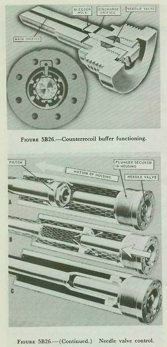
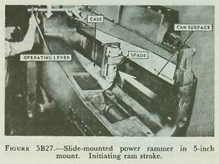
| Counterrecoil buffers. It was brought out earlier that any counterrecoil system must develop enough thrust to hold the recoiling parts in battery, and that in guns whose recoiling parts have appreciable mass the shock at the end of the counterrecoil stroke can be considerable. Counterrecoil buffers must consequently be incorporated into the gun mount to reduce this shock. These are not physically part of the counterrecoil system components described above; in present designs, they are located in the forward end of the recoil cylinders. Counterrecoil buffers are dashpot devices which use oil forced through small orifices to reduce the velocity of counterrecoiling parts at the end of the counter-recoil stroke. A typical design (similar to that in 5-inch guns) is shown in figure 5B26 (left), in three stages of operation. As counterrecoil movement begins, the housing and recoil cylinder move forward over the recoil piston. The buffer plunger, which closes off the after end of the recoil cylinder, is aligned to enter a hole in the recoil piston and piston rod. As the plunger enters the hole in the piston, the fluid caught therein is trapped, and can escape only through small passages in the plunger. At the end of the counterrecoil stroke (full battery position), the plunger is entirely nested within the recoil piston and piston rod. As is evident from figure 5B26, the flow of fluid through the counterrecoil buffer plunger is controlled by a needle valve. This valve can be set by moving a calibrated nut in the recoil cylinder head. (Figure 5B26, right.) By controlling the flow of the liquid through the discharge orifices or holes, the needle valve controls the speed of counterrecoil. The numbering on the calibrated valve nut makes it possible to set both buffers for equal, balanced functioning. For the proper procedure in setting these valves, see the OP on the mount. Where (as on 5-inch mounts) there are two recoil cylinders, each with a buffer, the valves must be set for balanced functioning. Note that the counterrecoil buffer regulates only the end of counterrecoil movement. This provides some control over the rate of fire of automatically loaded guns, but does not regulate the recoil stroke or most of the counterrecoil stroke. 5B7. Power rammers and mechanical ammunition feed The effectiveness of a gun per round, fired is concerned with such factors as range, efficiency of propellant, accuracy of fire, weight and initial velocity of projectile, explosive filler of the projectile, and the like. But the effectiveness of a gun as a weapon depends on the number of rounds per minute it can put into the target. It is here that mechanical loading and feeding devices are important. For convenience, these can be considered in two main categories. One is that of hoists, which are used to lift ammunition from the magazine to the gun deck level. These will be taken up in a subsequent article. The other category includes ammunition feeding and loading devices at the gun deck level. These include power rammers, slide-mounted ammunition loading gear, and equipment used to transfer ammunition from the hoist to the gun slide. In 5-inch mounts through Mark 39, in 6-inch turrets of Cleveland class cruisers and in bag gun turrets, separate power rammers are used for moving into the gun chamber ammunition which has been loaded into the slide. Figure 5B27 shows a slide-mounted rammer on a 5-inch mount. Here a piston in a long-hydraulic cylinder operates a reciprocating rubber-faced rammer spade or shell guard. The rammer is controlled by a rammer man. When a projectile and powder case have been deposited in the gun slide loading tray by the loaders, the rammerman depresses a lever on the rammer control rod. The rammer hydraulic cylinder, fed by a motor-driven pump on the slide, drives the piston, piston rod, and rammer spade forward, pushing the round into the chamber. When the cartridge case is in the chamber, it automatically releases the breech mechanism (as has been described earlier in this chapter) and the breechblock rises. When the gun fires, the rammer spade rides backward with the housing; this automatically (through mechanical linkage to a control valve) initiates the rammer retract stroke. The rearward-moving spade rides a camming groove in the slide which raises it well above the loading tray, so that it offers no obstruction to the extraction of the fired cartridge case. The spade is dropped to ram position manually. Except for this operation and for initiating the ram stroke, all rammer operations on this type of mount are automatic. |
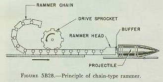
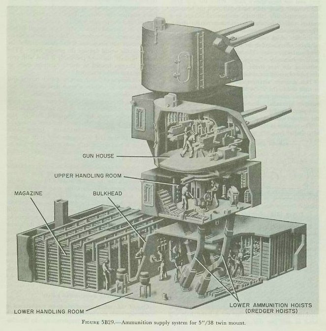
| This rammer arrangement is used in all 5”/38 mounts and in the 5”/54 Mark 39. The only notable difference among them is that in enclosed mounts the rammer hydraulic cylinder is shortened and a rack-and-pinion arrangement is used to make the stroke of the rammer space the proper length for ramming. The rammer in the 6-inch Cleveland class mount is of a similar type. Bag-type turret guns have long chambers, to accommodate (in 16-inch guns, for instance) up to six powder bags plus the projectile. This means that the rammer stroke must be very long. The length of a single hydraulic cylinder for such a rammer would be prohibitive. Such turrets are therefore equipped with chain-type rammers. Although the details of operation differ from one type of bag turret to another, all of them work on the principle illustrated in figure 5B28. A rotary hydraulic motor drives a sprocket which engages the links in a rammer chain. This is somewhat like an exaggerated bicycle chain, except that the straight chain will bend in only one direction (in the figure, upward only), and is stiff in the other. As the figure shows, in the type illustrated the links will remain straight without continuous support when extended horizontally. At the end of the chain is a buffer to protect the ammunition component being rammed. In bag-gun turret installations, the rammer operation is always under manual control, generally by regulating pump output to the hydraulic motor that drives the chain. The ramming operation requires two ramming strokes. In the first, the projectile is rammed home in a full maximum-thrust stroke, to ensure that the rotating band engages the rifling. Then the rammer is retracted, and the powder bags are rammed much less forcibly in a second stroke. After the second retraction the breech can be closed. Two strokes are necessary because the maximum-thrust stroke needed for the projectile would damage the powder bags. (The 5-inch rammer discussed previously is used with propelling charges housed in sturdy cartridge cases, so only one ram stroke is needed.) Newer designs of 3-inch mounts, 6-inch turrets, and 8-inch turrets all include a great deal of almost entirely automatic ammunition-handling gear. In the turrets, this equipment transfers the ammunition from the hoist to the slide (except that in the 6-inch design the projectiles must be manhandled through this stage), rams it into the chamber, and then disposes of the empty cartridge cases after firing. In the 3-inch gun, as in 20-mm and 40-mm machine guns,’ the ammunition is loaded manually into a loading device on the slide of the gun, and the ammunition is handled automatically from that point. But notice the distinction between 3-inch and larger ammunition-handling machinery, and that in true machine guns like the 20-mm and the 40-mm. In the latter, the ammunition-handling gear is operated by energy developed ultimately in the burning of the propelling charge. In the former, the ammunition-handling gear, though some operations are controlled by recoil and counterrecoil movements, is powered by an external source. In the 3-inch mount, the loader mounted on the slide of each gun is powered by an electric motor. In the turrets, the automatic loading equipment is driven by electrohydraulic gear. Because each type of mount or turret has its own design of ammunition-handling equipment, these units are described in further detail later in this textbook, each in connection with the mount of which it forms a part. 5B8. Power-driven ammunition hoists One of the earliest operations to be mechanized in connection with gun operations on naval war vessels was that of ammunition transportation. In the classic warship of Nelson’s day, black-powder propelling charges were stowed in magazines below the waterline, and were brought up to the gun decks by agile runners. Even with the slow rate of fire characteristic of contemporary cannon, there must have been delays and traffic jams in ships of the line of 80 guns or more, as runners scurried below to fetch their charges, then climbed up to the gun deck, the precious (and dangerous) charges guarded against sparks by being wrapped in the sailors’ shirts. One of the forerunners of modern shipboard ammunition supply systems was the mechanical hoist arrangement on the Monitor, which pioneered in naval warfare in so many other ways. Ammunition supply systems. Figure 5B29 shows in cutaway form the ammunition supply arrangements for a modern 5-inch twin mount. At the lowest level is the magazine, in which are stacked the propelling charges. The magazine partly surrounds the lower handling room, which is separated by a flameproof bulkhead from the magazine. Powder cases, which are stored in the magazine, are passed by hand through scuttles in the magazine bulkhead to the lower handling room. (Projectiles are normally stored in the lower handling room itself, in racks in the upper handling room, and on the gun-house bulkheads.) The powder cases and projectiles are then loaded into the 2 dredger hoists (1 for each of the 2 guns in the mount) which haul them up to the upper handling room. Each dredger hoist handles both projectiles and powder cases. On the upper handling room deck are located the upper ends of the 2 dredger hoists, and around the central column in the room are mounted the 2 sets of projectile hoists and powder hoists, 1 projectile hoist and 1 powder hoist for each gun. The handling room crew removes the projectiles and powder cases from the dredger hoists, loads the projectiles into the projectile hoists, and loads the powder cases into the powder hoists. In 5-inch hoists powder cases are loaded into the hoist base up to protect the impact-sensitive combination primer from being jarred by jolts on the base of the case. Five-inch projectiles also go into their hoists base up, so that their noses will rest in the hoist fuze-setting mechanism. Most of the propelling charges are stored in the magazine, and most of the projectiles are stored in the lower handling room. To begin ammunition service without delay, a number of complete rounds are maintained in ready racks in the upper handling room. For long periods of sustained fire, however, the entire ammunition supply system must be in action. With smaller mounts like the 3”/50, 40-mm, and 20-mm, hoists are relatively unimportant. Generally their ammunition is stowed in ready-service lockers nearby, and is hand carried to the mounts, though hoists may be used (depending on the installation) to replenish supplies. In turrets, the entire ammunition supply system, except the magazines themselves, is in-side the turret and rotates with it. |
 |
 |
 |
 |
 |
| Types of hoists. All gun ammunition hoists on modern United States naval vessels can be classified into one of the following categories: 1. Endless-chain. a. Hoist-or-lower multistage. b. Hoist-only single-stage. 2. Elevator. 3. Pawl. 4. Open-tube. The most widely used is the first class (in its two subtypes). The other 3 are used exclusively in turrets (though at least 1 rocket mount design employs No. 3). No.4 is an auxiliary. Endless-chain hoist-or-lower multistage hoist. This is the commonest type of hoist, and includes all dredger hoists, conventional 5-inch powder hoists, and a number of others used in turrets and elsewhere. Fundamentally, it consists of an articulated endless chain with supports or flights secured to it at regular intervals (fig. 5B30). Powder cases or projectiles are loaded by pushing them into the hoist in the path of the flights; when the hoist starts, the chain is driven upward until the next vacant flight is in loading position. When the next unit is loaded, the hoist goes up one more flight, and so on. Except in certain turrets, the hoist starts automatically when the ammunition detail is loaded, actuating a switch or hydraulic valve. Endless-chain hoists are driven by rotary hydraulic motors whose functioning is controlled by valves. Endless-chain hoists generally can be operated in reverse to lower ammunition units, as is required in taking ammunition aboard. In either mode of operation, the hoist moves one flight at a time, intermittently in the same direction. Only one side of the chain is used. Endless-chain hoist-only single-stage hoists. Like the preceding type, this hoist is an endless chain driven by a rotary hydraulic motor. It is used in 5”/38 and 5”/54 (Mark 39 only) mounts, and incorporates a fuze setter (described in a later chapter). Both sides of the chain are used (fig. 5B30). There are 2 flights, arranged so that when one is at the top of the hoist on one side, the other is at the bottom of the hoist on the other. The chain runs first in one direction, then the other, and the flights always move from all the way at the top to all the way at the bottom (or vice versa). The arrangement is similar to that of the old-time well with 2 old oaken buckets, one of which descended while the other went up. The projectile is loaded into one side, and automatically the hoist starts if the top is empty. As the loaded flight ascends, the empty comes down. The cycle reverses for the next projectile. This type of hoist can be used for hoisting only. It is not safe to attempt to lower projectiles in it. Elevator-type hoists. This kind of hoist is a single-stage system with a car which is moved up or down a hoistway. The car is secured to a hydraulically operated system of cables-a hoisting cable and a downhaul cable. Both are always in tension, and provide positive control of the car position. Unlike conventional elevators ashore, the car has no counterweight. The principal application for hoists of this type is to haul powder in bag-type turrets. Although protected by interlocks, such hoists are generally manually controlled. All loading and unloading points in such installations are protected by interlocked flametight doors. In 8-inch bag-type turrets (Baltimore class), there are two sets of elevators. One set hoists the powder bags to an intermediate flametight compartment where they are manually transferred to a second set, in which the bags are hoisted the rest of the way to the gun deck level. In the transfer compartment interlocks prevent the protective flametight doors of the lower hoist upper end from being open at the same time as the doors of the upper hoist lower end. This arrangement avoids the possibility of having a straight path open to flame from the gun deck level to the magazine level. In 16-inch turrets a single elevator-type powder hoist serves each gun, but operating procedures provide for opening the hoist upper doors only when conditions in the gun compartment arc safe. Pawl-type hoists. In this type of hoist the hoist tube is equipped with a set of spring-loaded pawl is a given distance (one “stage”) apart. The pawls protrude into the hoistway. Running the length of the hoistway is a jointed rod, or rack, similarly equipped with spring-loaded pawls one stage apart. The rod can be hoisted one stage by a hydraulic cylinder, then lowered back to starting position. This type of hoist is used for hoisting projectiles in 8-inch and 16-inch bag turrets, and in one rocket mount for hoisting rockets. The operating cycle is as follows: 1. A projectile is loaded at the lowest level. It is supported by the hoistway (stationary) pawl. 2. The hoist cylinder pushes the hoist rod upward one stage. At the beginning of the upward stroke, the lowest rod pawl engages the projectile base, and lifts it. The end of the upward stroke is just above the next hoistway (stationary) pawl. 3. Next, the rod is lowered back to starting position. The projectile is deposited on the hoistway pawl just below it. Another projectile can now be loaded into the first (lowest) stage. |
| 4. At the next upward stroke of the rod, the next higher rod pawl engages the projectile, and raises it another stage, where it can be supported by the next higher hoistway pawl. The process repeats until the projectile is at the top of the hoist. It must be removed (by loading into the gun) before another cycle can begin. Open-tube hoists. This kind of hoist is a simple open tube connecting one level of a bag-type turret with the next higher or lower level. Secured to the overhead above the tube is a small motor-driven hoist equipped with block and tackle, or with internal gearing and hoist chain. Normally the tube is closed by a flametight cap. The arrangement is used for hoisting or lowering projectiles when taking ammunition aboard or transferring it from one level to another. It is not designed for use as part of the normal path of ammunition from stowage point to the gun deck. Ammunition hoist safety features. Noteworthy safety features of ammunition hoists include: 1. Automatic hoists have doors or gates which will permit them to start up only after the ammunition item has been completely inserted into the hoist and the loader’s hands have been withdrawn. 2. Automatic hoists will not start automatically when loaded if the top level discharge point is occupied with ammunition. 3. All hoists in which powder bags are handled are equipped with flametight doors and interlocks to prevent an open flame path between lower handling room and gun deck. 4. Most power-operated ammunition hoists are equipped for manual operation in event of power failure. 5. Ammunition hoists are equipped with hydraulically actuated brakes or hydraulic locking to prevent loaded flights or cars from falling or drifting down the hoistway. 6. Most hoists are equipped with indicators to show whether there is an ammunition item at the receiving end of the hoist. 5B9. Miscellaneous safety features Some of the safety features of modern gun mounts and turrets have been taken up in connection with the other mechanisms or systems discussed above. But there are several additional noteworthy ones that should be taken up briefly. These are discussed in detail and illustrated in later chapters of this text, where appropriate. Salvo latch. This is a device that locks the breech closed. It can be opened only by deliberate effort. The function of the salvo latch is to prevent accidental manual opening of the breech in the event of misfire. Salvo latches are part of the breech mechanism of all guns larger than 40-mm, except for the very newest designs of automatically loaded guns like the 8-inch case gun used in Salem class turrets. It is also omitted from guns smaller than 3”/50. The salvo latch is a positive lock which is, in present designs, cammed to open automatically during recoil of the gun. It will not open automatically if the gun does not recoil. Safety link. The safety link is a metal strip that couples the breech yoke (in bag guns) or housing (in case guns) to the slide. It is intended to hold the gun in battery in the event of failure of the counterrecoil mechanism, or if the counterrecoil mechanism is disabled. It is used in guns equipped with hydropneumatic counterrecoil systems. If the gun is fired with the safety link engaged, the link will part. However, it is part of the normal gun operating procedure to disconnect and stow the link before firing. The link must be replaced when the mount is secured. Gas ejection. When a shot is fired from a gun, the bore is filled with residual powder gas. The gas is unsafe for humans to breathe, and is likely to be either flammable or actually burning; it is sometimes capable of spontaneous combustion when mixed with air. The function of the gas ejector, which is a part of every enclosed mount 5-inch and larger, is to force this residual gas out of the bore by a blast of air from the ship’s air system. In case guns the gas ejector is designed to open and shut off automatically during normal operation, though it can be operated manually. In bag guns the gas ejector goes on automatically when the breech plug opens, but must be shut off manually by the gun captain. When a gas ejector fails, the gun can continue firing, but caution is necessary to ensure safety. The rate of fire may have to be reduced. In bag guns, powder bags for the next round must not be exposed until fumes and embers have been cleared away. Inspection for smoldering embers is required in any event in bag guns, but it is especially important in case of gas ejector failure. |
| 5B10. Sighting and fire-control equipment With the increase in ranges of modern guns the problem of aiming the gun has become more complex. Sighting is considerably more complicated than merely pointing the gun at the target and firing. A projectile, when fired, travels in a curved path, not a straight line. This curved path is called the trajectory. Many factors affect the trajectory of the projectile. The major factor is the force of gravity, which causes the projectile to start falling as soon as it leaves the support the barrel provides. To fire at long range, the bore axis of the gun must therefore be elevated. Another force affecting the trajectory is the wind, which tends to blow the projectile off its course. Then there is the problem of the moving target. While target motion does not affect the trajectory, the gunner must lead the target the proper amount to hit. These factors and others complicate the problem of aiming a gun. The solution of this problem is in the field of fire control. The fire control system, in solving the gunnery problem, computes the angle by which the bore axis of the gun should be offset from the straight line between the gun and the target. This straight line is called the line of sight (LOS). It is the starting point in aiming the gun. With the line of sight on target, and the bore axis offset the correct amount, the gun is aimed for a hit. The offset is divided into 2 components, 1 vertical, called sight angle, and 1 horizontal, called sight deflection. Sight angle and sight deflection are the angular values of the offsets which the fire control system computes and transmits to the gun for use in aiming (fig. 5B33). The sights at the gun provide for establishing the line of sight and for introducing sight angle and sight deflection so that the gun’s bore axis will be properly offset. In gun mounts 3-inch and larger, sights generally consist of telescopes which move in train and elevation with the gun and also can be moved vertically and horizontally with respect to the gun bore axis to introduce sight angle and sight deflection. For accuracy at long range, telescopes give an enlarged view of the target. One telescope is provided for the gun pointer and another for the trainer. Each telescope has a reticle with a vertical and a horizontal crosshair to establish accurately the line of sight to the target. The pointer elevates or depresses the gun to get the horizontal crosshair on target, and the trainer trains the mount to get the vertical crosshair on target. Offsetting the sight telescopes with respect to the bore axis is the duty of a third member of the mount crew, the sight setter. The computed value of sight angle and sight deflection to be used is sent by telephone or indicated on dials to the sight setter. He has two handcranks which he uses to move the telescopes, one to shift them vertically by the amount of sight angle, the other to move them horizontally by the amount of sight deflection. The sight-setting mechanism has scales which enable the sight setter to crank in the precise values. On most mounts, there are two scales the sight setter can use to introduce sight angle (the vertical offset). One is graduated in minutes of arc, to display the actual value of the angle. The other is graduated in yards of range. This is called the sight bar range scale. It is designed for use against surface targets only. This range scale is used when the fire control system transmits the range to target (plus or minus corrections for wind, target motion, etc.), in linear units-yards. Most modern fire control systems transmit sight angle in minutes of arc. But some auxiliary systems still use linear values (yards on the sight bar range scale). Whichever scale is used, the sight setter turns the same handcrank to set the desired value. To introduce the correct amount of horizontal offset, the sight setter sets the value of sight deflection on the sight deflection scale, graduated in mils. (A mil is the angle subtended by an arc of length equal to one-thousandth of the arc’s radius-equivalent to 3.44 minutes.) This value is computed by the fire control system and sent to the gun. There it is set on the sight deflection scale by the sight setter with the deflection handcrank. In aiming a gun, the pointer, trainer, and sight setter work as a three-man team. The pointer sights through his telescope and keeps the horizontal crosshair on the target. The trainer sights through his telescope, keeping the vertical crosshair on the target. This establishes the line of sight. With no sight angle and sight deflection set, the bore axis of the gun will be directed along the line of sight. Here the sight setter enters the picture. Using the value of sight angle or sight bar range received from the fire control system, he sets this value on the proper scale by cranking the vertical offset handcrank. This moves the pointer’s and trainer’s telescopes off the target-usually moving them downward. The pointer then elevates with the elevation hand-wheel until he is back on target. In doing this, he elevates the gun as well as the telescope, and the bore axis of the gun is now elevated above the line of sight by the proper vertical offset (sight angle). Likewise, when the sight setter cranks in the value of sight deflection, the trainer’s and pointer’s telescopes move off the target to the right or left. The trainer then puts his vertical crosshair back on the target by training with the train handwheels. This trains the entire mount, offsetting the bore axis from the line of sight by the amount of the sight deflection. Thus the three-man team establishes the line of sight and also offsets the bore axis from the line of sight by the amounts of the sight angle and sight deflection, so that the projectile, when fired, will hit the target. |
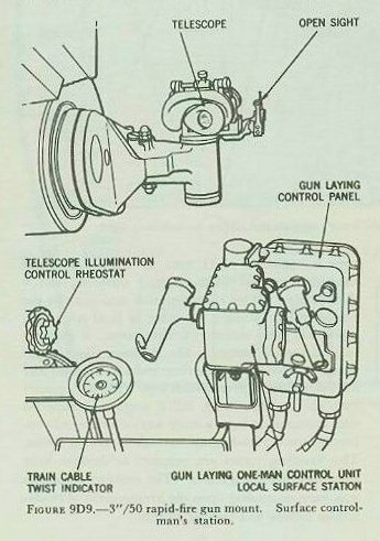 |
| 5B11. Types of sights The simplest type of sight now in use is an open sight consisting of a small peephole behind a vertical rod. The line from the peephole through the top of the rod defines the line of sight. Such a sight is used at the local surface control station of the 3”/50 rapid-fire mount; it is illustrated in figure 9D9. This open sight is used to bring surface targets into the view field of the adjacent telescope; it is not primarily designed for controlling gunfire. An almost equally simple type of open sight is the peep-and-ring sight; an example is visible in figure 9C1 installed on a 40-mm mount. The rear part of the sight is a peephole. The front part consists of concentric rings which are used not only to establish the line of sight but also to estimate lead angle for fast-moving air targets. Considerable skill and training are necessary for effective use of this sight. It is used nowadays only for local control in emergencies, or for slewing a gun mount toward the approximate location of a target. Telescopic sights permit more accurate sighting than open sights. There are two general types-the fixed-prism and the movable-prism. In the fixed-prism type the entire telescope is moved in order to offset the line of sight. The movable-prism type need not be moved because the prisms in the instrument can be shifted to offset the line of sight. The principles of prismatic telescopes are taken up in volume 2. A typical fixed-prism telescopic sight is shown on a 3”/50 mount, next to the open sight, in figure 9D9. Movable-prism telescopes used on 5”/38 mounts are shown in figures 8B23 and 8B24. A third general type of sight, the lead-computing sight, has movable optical parts and computing mechanisms which automatically offset the line of sight. Lead-computing sight mechanisms are discussed in volume 2. |
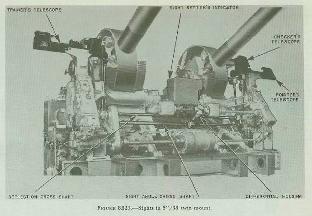 |
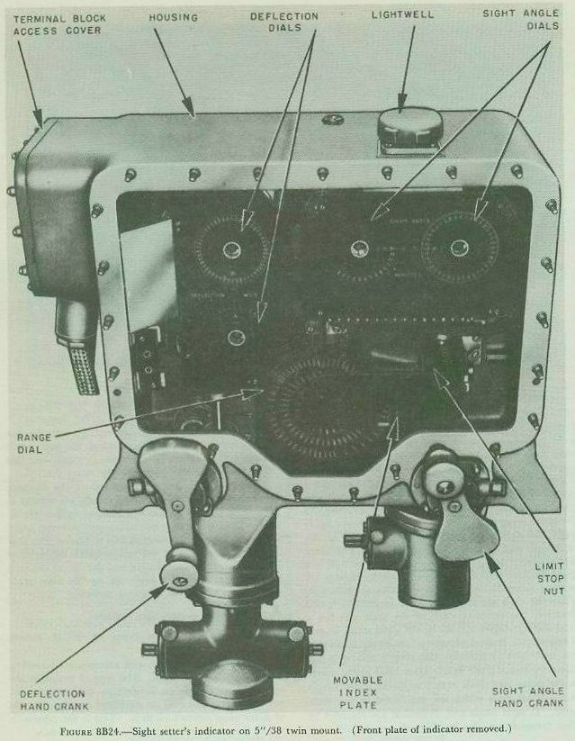 |
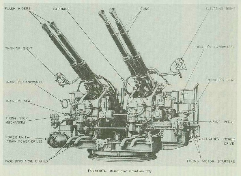 |
| 5B12. Train and elevation systems One important respect in which today’s naval gun differs from its ancestors is in the improvement in (a) the methods available for positioning it in train and elevation, and (b) the methods available for measuring its position-or, alternately, for shifting it to a prescribed position. Some smaller old-time cannon, called swivel guns, could be trained with relative ease, but, in general, training the old-time heavy cannon that poked their muzzles through the gun ports was a matter of getting the whole gun crew to drag it ponderously a few inches to one side or the other. Only a few degrees of train were possible anyway. It was better (and far commoner) to turn the whole ship. As for elevating, the old-time guns were breech-heavy, and a quoin or wedge under the breech could be pulled out to elevate the gun, or driven in to depress it. Again, it was easier, and much commoner, to leave this alone and let the ship’s roll decide the firing elevation. Long before aircraft made such methods as hopelessly antiquated as they sound, gun mounts and turrets were equipped with mechanical gear for training and elevating the gun barrel. But the development of aircraft in war accelerated these developments. In a modern gun mount, the trunnions are placed where the gun is approximately in balance. In conventional designs, handwheels connected through gearing to the training and elevating gear are arranged so that the pointer’s handwheels are at his station on the left, and the trainer’s at his station on the right. The pointer’s handwheels, in gun mounts, turn a pinion which rotates a gear sector on the slide called the elevating arc. (Figure 5B34.) The trainer’s handwheel, through gearing, turns a gear that engages the training circle in the stand. In bag-type turrets, where maximum elevation is limited and the mass of the parts to be elevated is especially great, the elevating gear turns an elevating nut which engages a screw pivoted to the gun slide. (Figure 5B34 inset.) Turrets of the case type must be capable of much greater elevations than are practical with this type of arrangement. They therefore use an arc-and-pinion type of elevating gear. All turrets, and mounts larger than 20-mm, use power drives as the normal method of positioning, though the pointer and trainer can readily switch to manual operation. Power drives and controls are discussed in more detail in chapter 10. In some later mounts all these conventional arrangements are not followed. For example, in the automatically loaded 3”/50 mounts, the gun cannot be manually elevated and trained from the gun-laying stations on either side of the mount. The controls there provide only for operating the mount through the power drives. The left gun layer’s station is used for positioning the mount when firing on air targets; the right gun layer’s station is in control for surface targets. Either station, or the director, may be in full control. When either gunlaying station is in control, mount train and elevation are both controlled by that station. Hence there is no “pointer’s” station or “trainer’s” station on this mount. And manual elevation and train are used only for positioning the mount for maintenance or alignment-checking purposes. |