| GENE SLOVER'S US NAVY PAGES NAVAL ORDNANCE 1937 CHAPTER XV THE NAVAL PROVING GROUND |
| HOME INDEX CHAPTER XV THE NAVAL PROVING GROUND Proving Ground Facilities Proof of Guns Proof of Mounts Proof of Powder Test of Projectiles Test of Armor Ranging Velocity Measurements. Pressure Measurements. Recoil and Counter-Recoil Measurements Experiments |
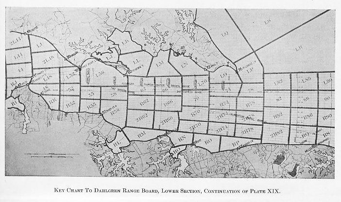
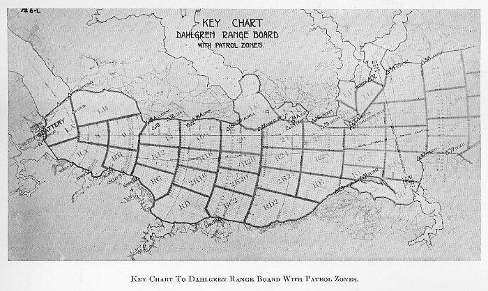
| CHAPTER XV. THE NAVAL PROVING GROUND. 1501. A naval proving ground exists for the purpose of conducting routine tests and experimental work on ordnance material involving firings, fragmentations, and the like which are necessary to insure the safety of material issued to service, to determine its suitability, and to develop material, where service tests are impracticable or undesirable. The first naval proving ground in this country was established as the Experimental Battery at Annapolis, in 1872, near the site of the present Engineering Experiment Station.’ From there it was moved to Indian Head, Maryland, on the Potomac River, about 25 miles below Washington. The water range available at Indian Head was only 17,000 yards, and the introduction of increased elevations for major-and medium-caliber guns necessitated a longer range. The present station at Dahlgren was begun in 1918 as the Lower Station, and all proof work was transferred there by 1923. The U. S. Naval Proving Ground is located at Dahlgren, Virginia, about 45 miles up the Potomac River from its mouth. A bend in the river at the entrance of upper Machodoc Creek permits the several batteries to front on a clear open-water range without mutual interference. The firing range available over water is about 45,000 yards and, by passing over a small tongue of land, the range available is over 90,000 yards. (See Plates XIX and XX.) |
 |
 |
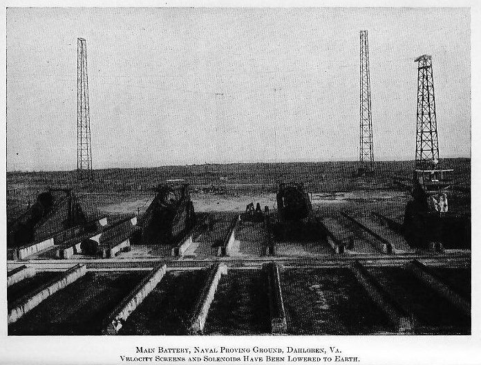
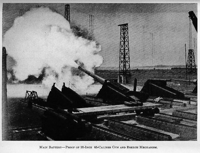
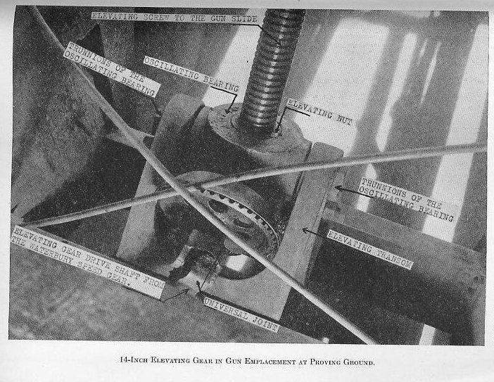
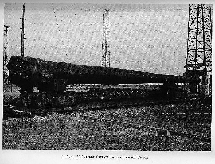
| The reservation includes 1,300 acres and provides for ample separation of (1) the proof area (the firing batteries with the laboratories and ammunition storage and preparation facilities), (2) aviation areas (seaplane hangar and ramp, landing field, and landplane hangar), (3) construction and supply area (shops, storehouses, and other facilities for station upkeep), and (4) the residential area (quarters for commissioned, enlisted, and civil personnel and minor community shops, etc.). All material is received by water transportation or by truck, the greater part coming on car floats from the Naval Gun Factory and from or through the commercial rail connection at the Naval Powder Factory at Indian Head, Maryland. 1 Some of the foundations and equipment can still be seen in the woods on the site of the present rifle range. All new guns and all relined guns, all broadside and anti-aircraft’ mounts, and representative samples of most other ordnance material, projectiles, armor, fuzes, bombs, etc, are subjected to proof or to tests at the Proving Ground before acceptance for service. PROVING-GROUND FACILITIES. 1502. Main battery.-The special proving-ground equipment includes concrete emplacements with pits to allow clearance for elevating screws, etc., means for tying down the girders, and electric power for elevating; and girders of plate and angle construction corresponding roughly to the gun girders and elevating transoms in turrets. In these girders, standard shipboard gear (deck lugs, slides, elevating gears, and guns) can be tested. The girders can be moved slightly in azimuth in the emplacements. (See Plates I, II, and XXII.) |
 |
 |
 |
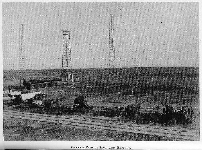
| 1503. Secondary battery.-Cast-steel tying-down circles with radial T-slots are embedded in concrete. On these any broadside or antiaircraft mount can be set and tied down with bolts slipped into the T-slots and clamps reaching on to the stand. (See Plate III.) |
 |
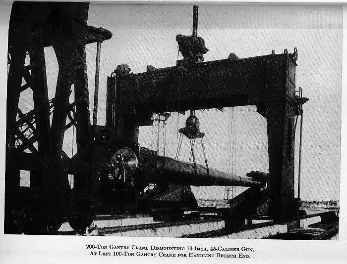
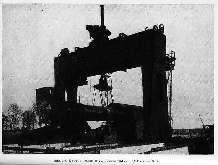
| Railway tracks permit the delivery of material directly to the battery, and locomotive cranes handle gear and all medium- and minor-caliber guns. For handling major-caliber guns, slides, girders, etc., there is a pair of gantry cranes which can move across the rear of the battery on tracks and parallel to the line of fire on special rails which straddle the unloading track and each emplacement. (See Plates IV, V, and VI.) |
 |
 |
 |
| Plate IV |
| Plate V |
| Plate VI |
| Plate III |
| Plate I |
| Plate II |
| Plate XXII |
| Plate XIX |
| Plate XX |
| 1504. Plate battery.-Emplacements and circles similar to those at the main and secondary batteries are required At this battery obsolete and “odd” guns can be employed, since all firing is at greatly reduced velocities and correspondingly low pressures in order to obtain the desired striking velocities, which normally have a fairly definite range table significance. (See Plate VII.) |
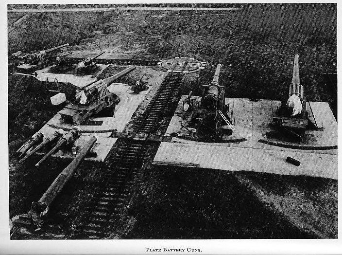 |
| Plate VII |
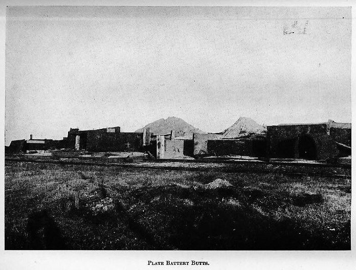
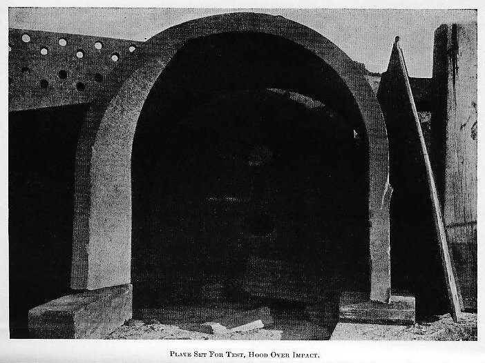
| 1505. Bombproofs.-At both the main battery and the, plate battery, concrete bombproofs are provided. These house the powder-rooms, the battery offices, firing switchboards, and all personnel during shots offering possible danger. At the main battery the powder-rooms include the constant-temperature room for bulk powder and the tank room for stacked charges, both of which are kept at 90 degrees F, and the weighing room which has facilities for weighing out charges and for stacking charges for 8-inch guns and above. 1506. Butts.-The butts are structures of discarded armor plate and timber to which plates are secured for tests Locomotive cranes are available for handling plate and other material, and sand diggers for shifting the sand piles back of the butts for recovery of projectiles. Plates are usually set vertically and the desired obliquity obtained by inclining the vertical plane to the line of sight from the gun. Hardwood blocking is placed between the butt plates and the test plate to maintain the obliquity and the whole secured with armor wedges (heavy wedges of scrap plate) at the foot and with tie rods and turn buckles at the top and sides. A hood over the area about the point of impact reduces the spread of fragments of plate and projectile. (See Plates VIII and IX and Fig. 1501.) |
 |
 |
 |
| Plate VIII |
| Plate IX |
| When projectile recovery is essential to the test, the butt is backed with a pile of sand in which the projectile lodges and from which it is dug with a, sand digger using an orange peel bucket. For fuze tests, where action behind the plate is desired, an open back butt is used, usually with a back plate far enough behind to detonate or stop the projectile if the fuze fails. Observations of fuze action are made from a heavily armored shelter at one side of the butts, using mirrors outside and above the shelter, which is closed except for a narrow observation area on the side away from the butts. 1507. Deck target.-There is a structural steel target, erected in an open field, and constructed to represent the decks of a ship This target is used to test bombs and bomb fuses when dropped from planes. 1508 Aviation activities -The aviation unit at the Naval Proving Ground is equipped with bombing and observation planes, both land-planes and seaplanes, and with a fighting plane in order to conduct tests of aviation ordnance material. The major part of the unit’s activities are concerned with test of bomb sights as received from manufacturers, calibration of new types of bomb sights for various sizes and types of bombs, and experimental work with new types of sights. Routine acceptance and experimental tests of such material as aircraft flares, float lights, parachute flares, practice bomb signals, etc., are also handled by the aviation unit in connection with the experimental officer. Observations of fall of shot to assist in identifying shots in triple salvos and flights for aerological data are made in connection with main battery firings. GENERAL PROVING--GROUND PROCEDURE. 1509. In all work at the Proving Ground, two points are kept constantly in mind, (1) to do the work with due regard for safety of personnel and material, and (2) to apply laboratory technique in the preparation of material, conduct of tests, and recording and analysis of data. The very nature of certain proving-ground work requires violating the safety precautions laid down for shipboard use, but in each such instance full cognizance of the fact is taken, the men are experienced, and the personnel and material involved are kept at a minimum. During the firing of any round involving possible danger, all personnel take shelter in concrete bombproofs or behind armor, and, for all routine firing on which it is possible, the gun crew takes shelter. In the preparation of material, dimensions are recorded carefully in order that identification may be certain and that departures from drawing dimensions may be noted. Careful examinations of guns and mounts prior to firing and after each round arc supplemented by bore-searching and star-gauging after firing. These latter examinations are made on station guns at definite intervals in their life rather than after each firing. Unless manifestly impracticable or undesirable, the velocity and pressure of each round fired is determined and recorded. Elevations are determined with a gunner’s quadrant and checked for each round with a tram. The line of fire is determined by theodolite and checked for each round by trams. 1510 Proof of guns -The proof of a gun (both new and relined) consists in firing enough rounds at and above its designed service pressure to insure that it will safely withstand normal service pressures The proof pressure for all modern major- and medium-caliber guns is 20 tons per square inch, an increase of about 11 per cent over their service pressures which range from 17 to 18 tons. 1511. Proof of mounts.-Normally mounts are proved at the same time as new guns, certain rounds being fired at 0 degrees and others at maximum elevation. The above proofs are conducted with station powders (accepted powders of excellent regularity) for which curves of velocity and pressures vs. weight of charge are kept corrected up to date. 1512. Proof of powder.-For the proof of new powders, new guns are desirable in order to avoid uncertainties due to erosion corrections. In the proof of a powder, the curves of velocity and pressure are developed by firing gradually increasing charges up to about 100 f. s. over service velocity. As a guide in selecting the charges, test sheets of similar powders are studied. For major-caliber guns using stacked charges, the weights of charge are selected and the charges stacked in time for them to remain in the tank room at a temperature of 90° F. for four days before firing. For other guns, the powder in bulk is placed in a constant-temperature room at 90 degrees F for the same period, and the charges are selected and made up as the firing progresses. When a new gun is not available, powders are proved in station guns, and an erosion check is fired with the station powder and standard station projectiles. This check, combined with the erosion curve which represents the average performance of guns of the same ballistic characteristics, determines the erosion correction for application to the worn gun curve to produce the new gun curve. The table below indicates the details of the proofs of gun, mount, and powder and the various combinations of the three. It should be noted that the proof and near-proof (91-96 per cent of proof pressure) rounds are fired with station powders. 1513 Test of projectiles -Projectile acceptance tests are of three types: Ballistic test against plate, in which tests the projectile must penetrate and remain intact as far as the cavity walls are concerned. The plate thickness, angle of obliquity, and striking velocity are set forth m the specifications for each projectile. Flight test to determine accuracy of flight and degree of approximation to range-table range when corrections for departures from standard conditions have been made (See Plate XXIII) |
| Plate XXIII |
 |
| Fragmentation test to determine if the detonation with service filler and fuze produces fragments comparable to those of standard projectiles. All projectiles must pass the flight test. Armor piercing and common projectiles must pass ballistic tests, the former against caliber plate if available or the thickest class A plate in use, the latter usually against class B plate or special treatment steel about one-half caliber thick. Armor-piercing, common, anti-aircraft, and anti-aircraft common projectiles must pass the fragmentation test. Fragmentation tests are required on only the first lot of each contract. Flight tests for armor piercing and common projectiles are required on only the first lot of each contract. All other tests are made on samples from each lot. (See Plate X.) |
 |
| Plate X |
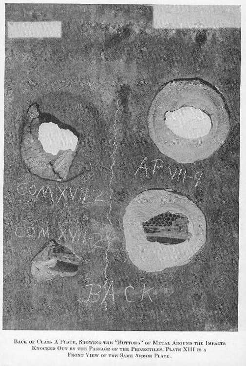
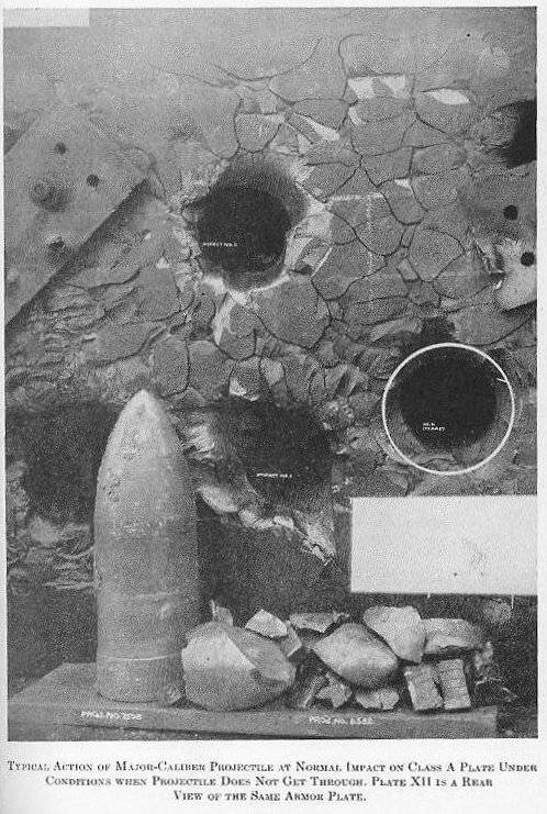
| Band recovery test.-At the option of the Bureau of Ordnance one or more projectiles under any contract may be fired into sand for recovery and examination of the rotating band and the characteristics of the band action. Illuminating projectile tests-The projectile bodies are brought to weight and subjected to the flight test. The fully loaded projectiles are given an acceptance test in which 15 from each lot are fired at short-, medium-, and long-fuze settings, with elevations sufficient to insure complete burning of illuminating element before hitting the water if normal suspension is obtained. The tests are conducted by day, and the performance of illuminant and parachute noted and timed from a boat at approximately the range of burst. 1514. Tests of ammunition details.-Generally speaking the specifications for manufacture of fuzes, primers, cases, tracers, etc., include the details of the tests at the Proving Ground. Whenever possible, these tests are combined with other routine or special firings to economize on ammunition as far as possible. In addition to the tests for proper functioning, all fuzes are subjected to safety tests and drop tests which are so conditioned as to defeat any inadequate safety features of the fuze, to determine whether it will stand rough handing and whether it is as nearly foolproof as possible. Tracers are followed visually in flight to ascertain the time of trace and whether normal action is obtained. 1515. Test of armor.-The ballistic test of armor plate is similar to the ballistic test of armor-piercing and common projectiles. The striking velocity and obliquity are laid down in the specifications and are such that, if the plate is of acceptable quality, the projectile will be rejected or at least will not pass completely through the plate. For class A plate two impacts are required, both must be met successfully and there must be no through crack into another impact nor to the edge of the plate (See Plates XI, XII, and XIII) |
| Plate XI |
| Plate XII |
| Plate XIII |
 |
 |
 |
| The requirements for thick class B plate are similar to those for class A. (See Plate XIV.) |
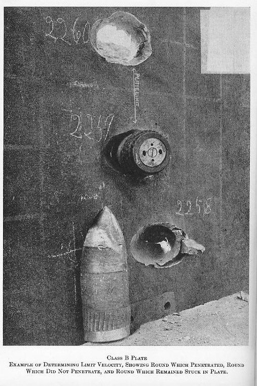 |
| Plate XIV |
| Thin class B plate and special treatment steel (up to about 3” thickness) are tested at high angles of obliquity. Only one impact is required, the projectile must be rejected, and there must be no through crack. (See Plate XV.) |
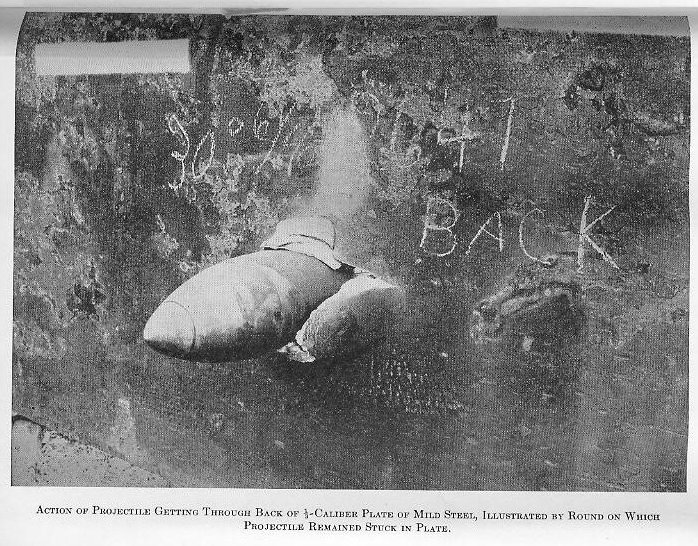 |
| Plate XV |
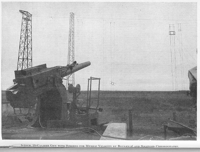
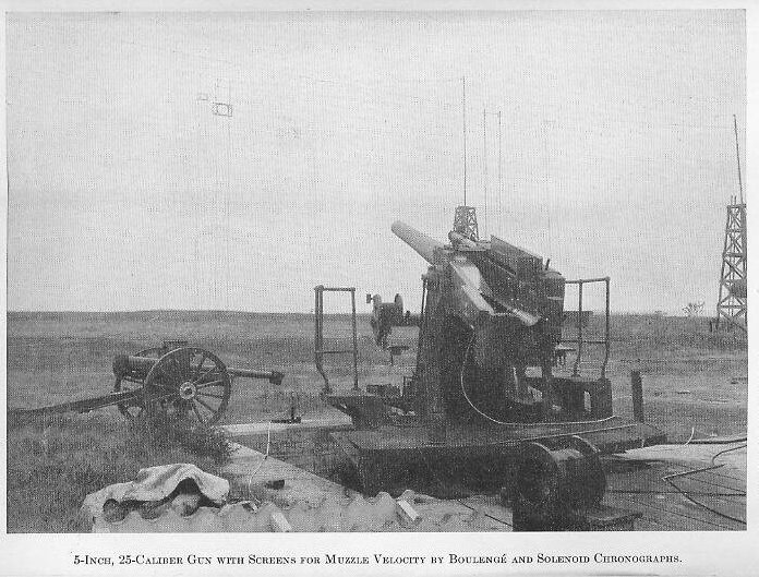
| Bullet-proof steel is tested with .30-cal. and .50-cal. armor-piercing bullets. The plate must reject the bullets and there must be no button thrown from the plate. 1516. Ranging.-The Dahlgren range is shown in Plates XIX and XX. At convenient points on or near the river banks on both sides of the river, range stations have been established and located accurately by triangulation. At each of these stations a theodolite may be mounted, shelter for the range-man is provided, and at most stations there is telephone or radio communication with the bridge at the battery. Appropriate stations for the point of fall expected are manned and the splash on each round is located by angles from at least three stations. The rangemen also note and report any peculiarities in flight. One or more range boats patrol the range, keep slow moving boats clear of the line of fire, instruct other craft when and where they may cross, and inform the officer in charge of firing whether the range is clear. Authority to control traffic on the river as necessary to permit firing is delegated to the Inspector of Ordnance in Charge, Naval Proving Ground, by the Secretary of War. The range board is a bronze chart of the range on a scale of 1 cm. equals 100 yards, with lines of fire for each degree and range circles every 1,000 yards. At each range station, a hole is drilled to receive a station plug, cut to a half cylinder above the board. A sheet of tracing-paper is stretched over the board and the angles recorded by the range men are plotted with a three-arm protractor. The accuracy of observation is such that a failure to obtain a very minute triangle, or to have the three lines intersect in a point, is rare. All measurements on the range board are referred to the reference point in range and to the line of fire used in deflection. These ranges and deflections are corrected for the distance of the gun to the right or left of the reference point and ahead of the reference line, giving the uncorrected range and drift. The corrected range is obtained by applying to the uncorrected range the range-table corrections for variations from standard conditions Aerological data -As a matter of routine, the aerological unit takes upper-air soundings by following with a theodolite a small sounding balloon, inflated to a definite weight to give a fixed rate of ascent. Plotting the successive angles of elevation and azimuth gives a curve from which the force and direction of the wind at various levels may be determined. During all rangings, special “wind aloft” observations are taken, and from them is derived a ballistic wind. This is made up by applying to the wind in each zone of 1,000 feet altitude up to the maximum ordinate for the firing, a weighting factor based on the time the projectile remains in that zone. When ranging for range-table data, altitude temperature data are obtained by sending a plane up to the probable maximum ordinate. The plane carries a thermometer which is read after leveling off at each 1,000 feet ascending and descending. PROVING-GROUND TECHNIQUES. 1517. Velocity measurements.-Essentially, the muzzle velocity of a projectile is obtained by measuring the time interval between the projectile’s passages of the planes of two screens rigged at a known distance apart along the line of flight. These data give the mean velocity midway between the screens, and a correction, based on the type of projectile, the distance from the muzzle to the midpoint, and the instrument velocity, gives the muzzle velocity. |
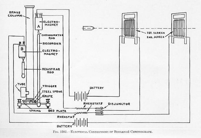 |
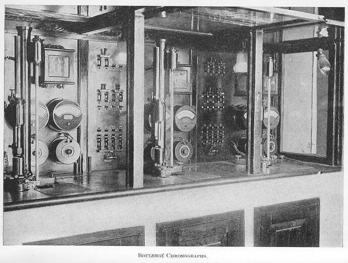
| 1518. Boulengé chronograph. (See Fig. 1502.)-This instrument, invented many years ago by an officer of Belgian Artillery and developed abroad, is still in common use at proving grounds in all countries. It measures the time interval by recording the difference in time of fall of two rods, suspended by electromagnets. The longer (chronometer) rod, being released when the projectile breaks the first screen, is nicked in its fall by a knife released by the shorter (registrar) rod whose electromagnet is in series with the second screen. Before taking any records with the instrument, the chronometer rod, enveloped by its recorder, is suspended from its magnet and then the knife is released by the trigger. A mark is made near the bottom of the recorder. This mark is the origin, or zero, from which all heights of fall of the chrometer must be measured. |
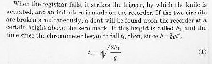 |
| It is evident that t1 is the time required by the instrument to make a record, and includes any difference in the time required for demagnetization of the two magnets, the time occupied by the registrar in falling, and the time required for the knife to act. Both circuits pass independently through an instrument, called the disjunctor, by which they may be broken at the same instant. The mark made by the knife when the circuits are broken by the disjunctor is called the disjunction mark and its height, h1, is fixed. The disjunction time t1, accordingly is always known. When the circuits are broken by the projectile, the chronometer circuit is broken first, and the chronometer begins to fall before the registrar. Therefore, the second mark made by the knife will be found above the disjunction mark. If h2 represents the height of the second mark above the zero and t2 the corresponding time, then, |
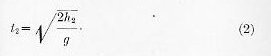 |
| Thus t2 denotes the total time that the chronometer was falling before the mark was made. To obtain the time, t, between the two breaks, we must subtract from this total time, t2, the time t1, used by the instrument in making a record. Then, |
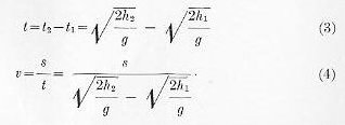 |
| where v represents the mean velocity of the projectile while passing between the screens, and s the space and t the time between the screens. It is seen from Eq. (3) that the difference of the times, and not the difference of the heights, must be taken. This indirect, method of arriving at the time, t, by taking the difference of two time intervals, is characteristic of this instrument and explains its precision. Knowing the value of g at the Proving Ground, these times of fall and hence the instrument velocity, can be computed In proving-ground practice, three instruments are used simultaneously and the mean of the three taken. To avoid confusion of records, the plated aluminum tube on the chronometer rod is turned slightly after each round (See Plates XVI, XVII, and XVIII) |
| Plate XVI |
| Plate XVII |
| Plate XVIII |
 |
 |
 |
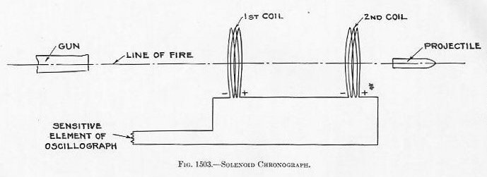
| 1519. Solenoid chronograph -This system depends on the principle that when a magnet is thrust into a coil of wire an e.m.f., is set up and, if the coil be part of a closed circuit, a current will flow. The wired screens of the Boulengé system are replaced by frames, each wound with a coil of wire. The coils are connected in series with each other and with the sensitive element of an oscillograph. The projectile is magnetized by holding it in the field of a fixed coil with a heavy current flowing for a few seconds immediately before loading. The passage of the projectile through each screen sets up a current whose occurrence is recorded by the oscillograph. (See Fig. 1503.) |
 |
| 1520. Oscillograph.-This is a commercial instrument adapted to proving-ground uses. It consists essentially of a highly sensitive galvanometer carrying a small mirror on the suspension wire of its sensitive element; a small arc light with a system of lenses and prisms for distributing the light; a 500-cycle tuning fork, kept vibrating at its natural frequency by a magnetic field, which carries on each tine a slotted vane; and a moving photographic film or direct-printing photographic paper. The slots in the vanes pass each other 1,000 times per second, and light being directed at their point of passage and thence to the moving strip, a series of lines 0.001 second apart is made. A beam focused on the mirror of the sensitive element reflects a steady beam to give a straight line on the moving strip until the momentary current flows This current causes a deflection of the element from neutral to each side and back to neutral, resulting in a kick, resembling a sine curve, on the strip. The time between coils can be read directly from the strip, and the instrument velocity so determined. (See Fig. 1504.) |
| LARGE PICTURE GOES HERE UNDER CONSTRUCTION |
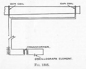
| The proving-ground oscilograph has an attachment which numbers and dates each strip before the record is made, and another which automatically develops and fixes the record in a few seconds. This overcomes the disadvantage in earlier types of waiting for dark-room development before obtaining the velocity. Various devices are employed for opening the shutter over the moving strip, depending on the probable time between firing and the projectile’s passage of the first coil. Other oscillographs are available with revolving drums for carrying the strip and multiple elements permitting several simultaneous records. The instruments find numerous applications in all proving-ground experimental work involving the measurement of time intervals, since the elements can be connected so that the making or breaking of a contact will offset the line on the strip. The oscillograph is now the primary instrument for measuring velocities of projectiles. Its advantages over the chronograph are greater precision, and the fact that a permanent photographic record is made which can be filed for future reference 1521. Aberdeen chronograph -This instrument, developed by the Army’s Aberdeen Proving Ground, makes its record on a sensitized strip carried inside the rim of a shallow drum rotating at a fixed speed around its vertical axis. The screens in this system are of two very thin metal plates with an insulating sheet between. The passage of the projectile short-circuits temporarily the two faces of the screen. The circuit for each screen contains a source of power, condensers, and the primary of a transformer. Each secondary circuit has a. break between the drum and a fixed pointer close to its inner surface. The closing of the break at the screen causes a spark to jump the latter break and make a point on the sensitized strip. The points for the two screens being in different horizontal planes, the distance between points can be measured in the direction of rotation of the drum. This distance, with the linear speed of the strip (from the inner circumference and the fixed rate of rotation), gives a measure of the velocity between the screens. Calibration is effected by means of a device dropping a ball a short fixed distance. At Dahlgren, the Aberdeen chronograph is used chiefly for measuring velocities of small-arms bullets at the light armor butts. The small size, simplicity, and ruggedness of the Aberdeen chronograph make it available for shipboard use, where it is valuable in the measurement of the velocities of aircraft catapults. The Aberdeen screens find frequent use in oscillograph circuits instead of solenoid coils when firing minor-caliber projectiles. 1522 Gun coil chronograph.-A system developed at the Naval Proving Ground winds the coils directly on the gun and maintains a current through these coils and the primary of a transformer The secondary of the transformer is m series with the oscillograph element The passage of the projectile, whether magnetized or not, through the plane of each coil causes a momentary change in the total flux The corresponding change m current produces a kick on the oscillograph record. This system has particular application for velocity measurements during shipboard firings in case the occasion arises, and furnishes perhaps the only satisfactory method for directly measuring the velocity in the bore. (See Fig. 1505.) |
 |
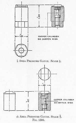
| 1523. Pressure measurements. Crusher gauges.-For measuring the maximum pressure in the powder chamber, the crusher gauge is in common use. It consists of a copper-jacketed steel cylinder, closed at one end by a copper-jacketed steel screw plug, and having a small piston with a lapped fit. Between the piston and the plug is placed a small copper cylinder, called a “crusher” disc. The plug being screwed home, the piston is set firmly against the disc, a copper gas-check cup is inserted above the piston, and the hole is filled with tallow. Three such gauges are placed in the bottom of the case for case guns and are tucked under the rear of the last bag in bag guns. The gas pressure forces in the piston, compressing the disc. The difference in the disc’s lengths before and after firing, determined by micrometer caliper, is a measure of the maximum pressure in the gun. For all except minor-caliber firings, the area of the gauge piston is 4-sq. in.; for minor calibers the area is sq. in. In the manufacture of discs, representative samples are subjected to various pressures in a hydraulic press and the corresponding compressions plotted as a curve. From this curve is prepared a table for battery use, giving the pressure corresponding to each 0”.001 compression. To avoid excessive compressions and the effect of the kinetic energy of the piston acquired during a relatively long travel, an initial compression of 9 tons is given to discs used for measuring pressures greater than that. For near-proof and proof rounds six gauges are used, for all others three. (See Plate XXI and Fig. 1506.) |
 |
| 1524. Recording gauges.-Since the crusher gauges can give only the maximum pressure, and that only within a probable error of about 0.3 ton, the need for some means of recording against time the development of the pressure as well as its values has long been felt. The oscillograph, of course, affords the recording element, and several types of gauge elements have been developed. All of them are still in the status of laboratory instruments and are not adapted to the routine measurement of pressures. One type employs a stiff spring of low period which receives the pressure from a piston and, by its movement, closes or opens a series of electric contacts, suitably connected to the oscillograph element. Another utilizes the Piezo-electric principle by which a quartz disc under pressure along certain axes develops electromotive force directly proportional to the pressure. A stack of such discs is arranged to receive the pressure and the current developed in the circuit is amplified and recorded by the oscillograph elements Gauges such as these are usually assembled in gauge bodies which screw into the face of the mushroom, the necessary leads coming out through the mushroom stem. Development of these gauges in order to produce systems suitable for routine use is being continued. 1525. Recoilmeter-Velocities of recoil and counter-recoil are determined from recoilmeter records A rod of alternate sections of conductor and insulator is secured to the yoke, and, on recoil moves through a set of bearings fastened to the slide, with a contact point at one bearing By connecting the rod and contact point in series with an oscillograph element, a record giving a series of alternate makes and breaks is obtained From the times between successive contacts and the known length of the segments, a time-displacement curve is obtained, and the curve of velocity-of-recoil derived. While the same system is competent to record the counter-recoil, a long record would be required and the usual practice is to use a duplicate system opening the second oscillograph shutter later. 1526. Pressures.--For recording the pressures developed during recoil and counter-recoil in the recoil cylinder, modified Tabor indicators are used (Plate XXI). The modifications are simply to adapt it for proving-ground mounting and to insure the indicator’s withstanding the pressures which are considerably greater than those encountered in ordinary steam engineering practice. Two indicators are required, one at the rear head for recoil pressures and one at the forward head for counter-recoil pressures. |
 |
| Plate XXI |
| 1527. The gunner’s quadrant consists of a flat base with a pivoted arm carrying a spirit level. The arm is set at the reading corresponding to the desired elevation, the quadrant is put on the gun, and the gun is elevated until the bubble centers. It is then at the desired elevation. (See Plate XXI.) The Vickers gun clinometer is a more accurate instrument. The level arm is adjusted to the degree next below the elevation desired. By turning a screw handle, a needle arm on a large arc graduated to minutes is worked so that the setting of the instrument to degrees and minutes of elevation is done more quickly and more accurately than with the simple type of gunner’s quadrant. EXPERIMENTS 1528 Experimental Work -While the routine tests of service material are an important function of the Proving Ground, experimental work for the test of new materials or methods, the checking of principles, the development of improved proving-ground techniques, and the investigation of difficulties encountered in service are of equal importance. Experimental facilities.-In addition to the regular chronographs and oscillographs, there are available for experimental work multi-element oscillographs and cathode-ray oscillographs. Certain guns are set aside for experimental work in order that the preparation of apparatus may proceed without conflict with routine firings. One such gun is pierced at various points along the bore to allow insertion of pressure gauges, thermo-couples, or contact points for taking interior ballistic data while its mushroom is fitted for recording pressure gauges. Another has grooves cut in the slide cylinder to allow placing gun coils at small intervals in the space covering the early stages of projectile movement. Data on the flight of projectiles and bombs are obtained with projectile cameras in which a series of five or seven lenses records images on a rotating film. The focal plane shutter has stepped slots to open but one lens at a time. The shutter and the film drum rotate in opposite directions, the film being run at the expected speed of and in the same direction as the image of the bomb or projectile. This results in stopping the image on the film, giving sharp pictures at short intervals. The attendant blurring of stationary objects is of no importance. A high speed motion-picture camera capable of 200 exposures per second and photographing in each frame a 0.01-second stop watch is of frequent use in making studies of fuze action, bomb flights, machine gun mechanisms, etc. 1529. Bamberg theodolite system.-Data on bomb trajectories, flight of planes, etc., are obtained by the Bamberg recording theodolite system. At each of three instruments, permanently mounted on well-separated stations, the readings of the elevation and azimuth scales are recorded simultaneously on motion-picture film. The interval between records is controlled by a tape chronograph at the laboratory. The cross wires of each theodolite having been kept on the object during the run or flight, the angles recorded, by a laborious system of plotting, produce a series of points representing the path of the object in flight. |