| NAVAL ORDNANCE AND GUNNERY, VOLUME 1 CHAPTER 9 AUTOMATIC WEAPONS |
| HOME INDEX Chapter 9 Automatic Weapons A. Introduction B. 20-mm aircraft gun C. 40-mm guns and mounts D. 3"/50 rapid-fire guns and mounts |
| D. 3ö/50 Rapid-Fire Guns and Mounts 9D1. General The 3ö/50 rapid-fire guns are semiautomatic guns with automatic power-driven loaders, installed in dual-purpose open twin or single mounts. They are weapons primarily intended for defense against aircraft, but are so equipped that they may be used against surface targets. They were planned during World War II when a need developed for a rapid-fire gun with a larger explosive projectile. The 40-mm mount, the best rapid-fire gun at that time, was often making hits that were not stopping suicide planes or dive bombers short of their targets. The 3ö/50 mount was not completed in time to be used in combat in World War II, but it has proved itself in practice firings to be very effective. This mount is now replacing 40-mm on all types of combat ships. The twin mount shown in figure 9D1 is dimensionally interchangeable with the 40-mm quad mount. The single 3ö/50 rapid-fire mount, which is similar in most respects to the twin, is designed to be substituted for the 40-mm twin mount. |
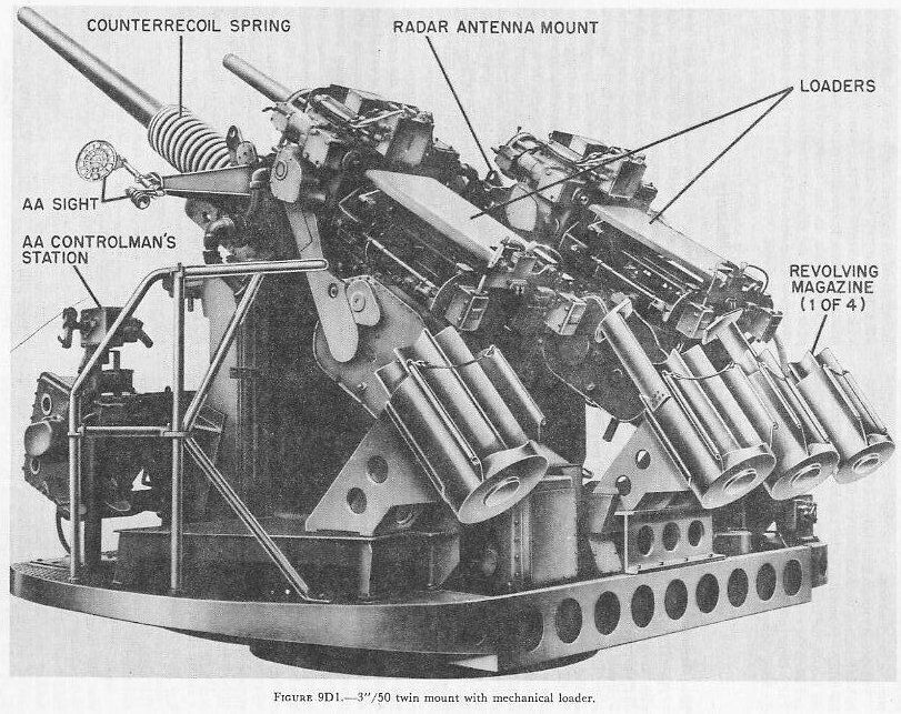 |
| The barrel of the 3ö/50 is a one-piece, rifled, chambered tube, with its breech end locked to the housing by a bayonet-type joint. The housing contains the breech mechanism and is supported in the slide. The breech mechanism is a vertical sliding-wedge breechblock type with several additional features. The breechblock has two mechanisms for lowering it against the action of a breech-closing spring. One is a hand-operating lever employed only for initial round loading or for servicing or unloading the gun. The other breech-opening arrangement is an automatic recoil-operated cam-and-lever device. When the breech is open, two mechanisms function, alternately, to hold the block against the action of the closing spring. One is a stiff-leg type of breech hold-down mechanism which serves as a positive lock, holding the block and locking it until the gun is loaded. It prevents breech closing until it is first released and then displaced from its holding position. The other holding mechanism is similar to that used in the 5ö/38 gun, in which the two extractors hold the breechblock down by engaging its pallets. However, their arrangement in the 3ö/50 is such that, when they complete their empty-case extracting action, the extractors are poised above the pallets in the lowered breechblock, and function to hold the breechblock down only if the other device fails. This arrangement reduces the effort required to trip the extractors when a rammed round of ammunition engages them. The gun barrel and housing are supported by the slide. When the gun is fired, they move backward and forward on bearings in the slide. A hydraulic recoil cylinder brakes rearward motion. A large counterrecoil spring drives the gun forward into battery. The slide, gun, and housing are supported by the carriage. The trunnions, which are integral with the slide, rest in roller bearings at the top of the carriage. A large elevating arc attached to the bottom of the slide is concentric with the trunnions. It meshes with the elevating pinion of the mount, elevation power drive system. The 3ö/50 gun assembly stand is a deck-flange ring-shaped design with dimensions identical to those of the 40-mm stand. It includes the training circle and the stationary roller path. The mount is driven in train by a power motor which drives the training pinion and pulls the gun, slide, and carriage around the training circle on the stand. General characteristics. The 3ö/50 gun has the following general characteristics: Bore_____________________________3-inch Length___________________________50 calibers Muzzle velocity____________________2,700 feet per second Range, horizontal__________________ 13,100 yards Range, ceiling _____________27,300 feet Rate of fire (design)_________________ 45 rounds per minute Ammunition type________________ fixed, electric primed Fuze type________________________ VT, PDF, BDF Weight complete weapon___________6,230 pounds Dimensions, over-all: Muzzle to rear end____16 feet Width______________ 38 inches Height_____________ 56.8 inches In many features of design the 3ö/50 rapid-fire gun differs markedly from conventional automatic guns. These differences are chiefly in the automatic loader and the breech mechanism modifications to accommodate the automatic loader. It will be mainly these differences that will be taken up in this chapter. |
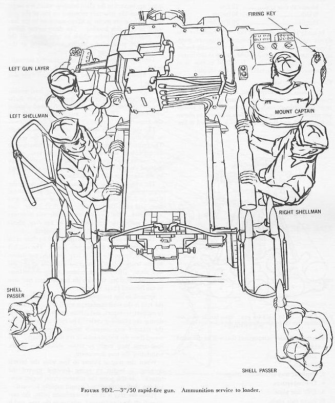 |
| 9D2. Automatic loader The loader is an independent, electric power-driven machine mounted on the after part of the slide. It mechanically loads each gun at the rate of 45 rounds per minute as long as ammunition is served, as shown in figure 9D2, and the firing control is operated to fire. The major loader components that will be discussed are as follows: 1. Loader drive unit. 2. Hopper. 3. Transfer tray and shell carriage. 4. Control system. 5. Left side plate. 6. Right side plate. The loader drive unit consists of a 3-horsepower motor and various chain and gear drives. Most of the latter are located in the main housing, which is a large, square, box-like structure mounted on top of the gun slide. The drive motor is flange-mounted to the forward face of this housing. The drive motor drives the gearing and chains which in turn cause all the mechanical parts of the loader to function at the proper time and in the proper sequence. The hopper, into which the ammunition is manually fed by the two shellmen, is located directly abaft the main housing and is secured to the left and right side plates. The heart of the hopper is the hopper feed mechanism, which consists of right, center, and left shaft-and-sprocket units and right and left round-aligning attachments. The aligning attachments ensure that the ammunition is correctly loaded by the shellmen. |
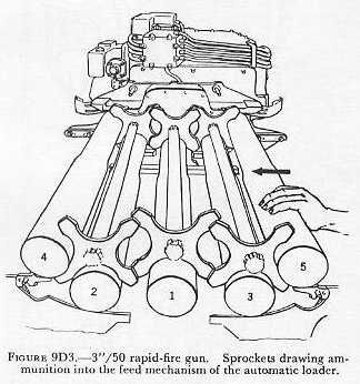 |
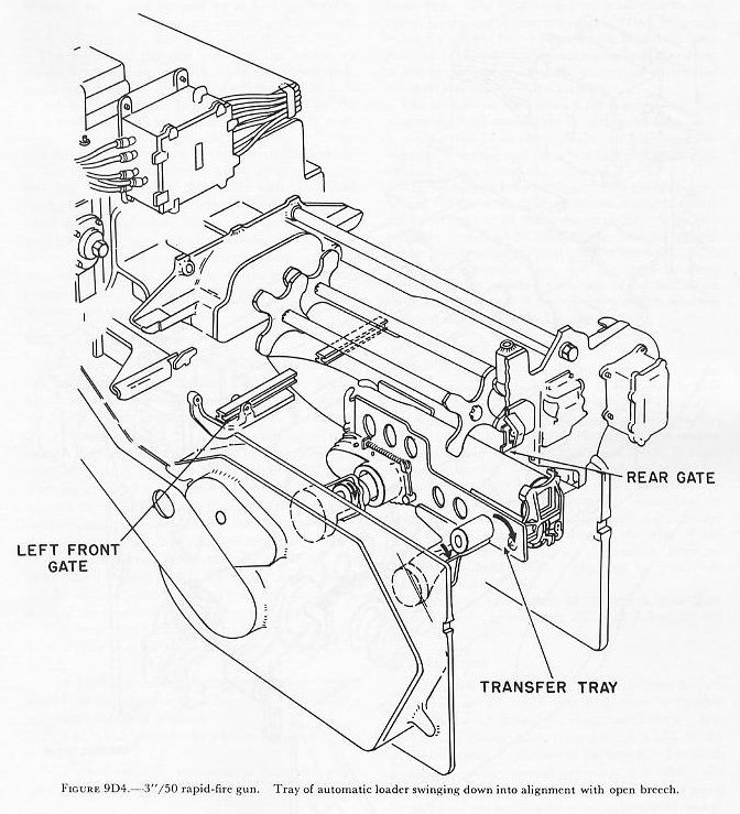
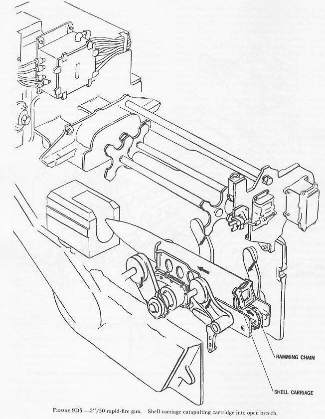
| The right and left sprockets revolve intermittently in one direction to move ammunition to the center. The center sprocket revolves in alternate directions to accept rounds from right and left sprockets. After five rounds have been loaded, the first round will be indexed (loaded into the transfer tray for catapulting) by the center sprocket. See figure 9D3. The transfer tray and shell carriage unit is the loader component that moves each round of ammunition from its index position down into line with the gun bore, and catapults it into the breech chamber. See figure 9D4. The tray is a rectangular box structure with 2 sprockets, 1 in each end of the tray, about which the endless ramming chain is looped. The tray is supported and positioned by four arms pivoted in the right and left side plates. The two left tray arms, hence the whole tray assembly, are driven by the transfer-tray drive gears mounted in the left side plate. Drive for the rammer chain comes from concentric shafting through the left forward tray arm to the forward chain sprocket. Secured to the rammer chain on the upper part of the tray is the shell carriage, a small L-shaped casting, to support, transport, and release the round on the tray during the ramming cycle. The cycle of operation of the transfer tray assembly begins when an indexed round from the hopper seats in the shell carriage. The four arms then begin to rotate about their pivots, translating the tray downward. When the tray is almost in line with the breech opening, it begins to swing forward toward the breech. At this point the rammer chain begins moving the shell carriage and round rapidly forward. |
| When the tray is at its forwardmost point, the carriage is all the way forward, relative to the tray, and is releasing the round, which travels on into the breech as shown in figure 9D5. The tray then reverses its direction and moves aft and up to pick up another round. During this time the ramming chain moves aft to reposition the shell carriage on the tray. |
 |
 |
| The right and left side plates of the loader are similar steel forgings-roughly 4 feet long, 2 feet deep, and 6 inches thick-secured to the right and left sides of the gun slide respectively. They support all the loader subassemblies except the drive gear. In addition, each includes many loader operating and control devices and elements of the breech mechanism. The loader control system synchronizes and interlocks the components of the loader with the breech mechanism and with each other. It consists of electrical circuits, solenoids, selector switches, automatic switches, firing keys, electrical interlocks, and other items. The mount captainĺs control panel is a combination control and indicator station for the loader control system. (It will be described in more detail in a later paragraph.) 9D3. Breech mechanism The breechblock is a vertical sliding-wedge type, similar in principle to that of the 5ö/38. The breech-block moves as the operating shaft rotates. Much as in the 5ö/38 design, in automatic operation the breech-block is lowered and the operating spring is compressed on counterrecoil when the operating-shaft crank is rotated by the operating-shaft cam plate. The breech is closed by the operating spring. A manual breech-opening mechanism is provided. A conventional, positive-type salvo latch on one end of the operating shaft prevents unintentional opening of the loaded breech before the gun has fired. The breechblock is fitted with a firing mechanism, which will be discussed later. Some of the new design features of the breech mechanism are as follows: 1. A breechblock hold-down mechanism holds the breech open until the loader completes delivery of a round. 2. A breech interlock mechanism prevents repetition of the loading cycle until the round has been fired and the breechblock dropped. 3. A shell lock prevents the rebounding of a rammed cartridge. 4. A novel extractor arrangement eliminates resistance to ammunition-ramming action. |
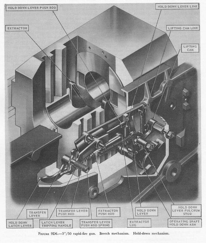 |
| 9D4. Breech hold-down mechanism Other guns of similar design usually make use of the extractors to hold the breechblock down until a round is rammed. However, the 3ö/50 rapid-fire gun makes use of the breech hold-down mechanism instead. See figure 9D6. The hold-down lever is a vertically positioned lever pivoted near its center. When the gun is in battery and the breechblock is in its held-down position, the hold-down lever bears on the hold-down arm of the breech operating shaft, preventing rotation of the shaft and closing of the breech. The hold-down latch lever is the positive latch that secures the hold-down lever in place when the latter is holding the block down. The latch lever is disengaged in normal operation by a cam pin on the front right arm of the transfer tray. The hold-down lever is released from the hold-down arm of the operating shaft in normal automatic loading by movement of the right extractor. When the extractor is carried forward by the rammed ammunition, the extractor push rod is thrust rearward. This actuates the transfer lever, and the thrust is transmitted through another push rod to the hold-down lever, moving it clear of the operating shaft hold-down arm and allowing the block to rise. 9D5. Extractors The extractors are very similar to those in the 5ö/38, except that the inner lugs do not normally bear on the block pallets but are poised above the pallets in a free position. In this free position, the extractors do not impose any appreciable resistance to the ammunition-ramming action, an important factor in rapid automatic loading. While the breech is opened, the extractors are held in their correct position by extractor push rods, which also aid in extracting the empty case. The right extractor push rod is longer than the left and extends through the rear of the breechblock, where it engages the transfer lever for use in the hold-down mechanism as previously described. In the event of a failure of the breech hold-down mechanism, the breechblock will be held down by the inner lugs bearing on the pallets. |
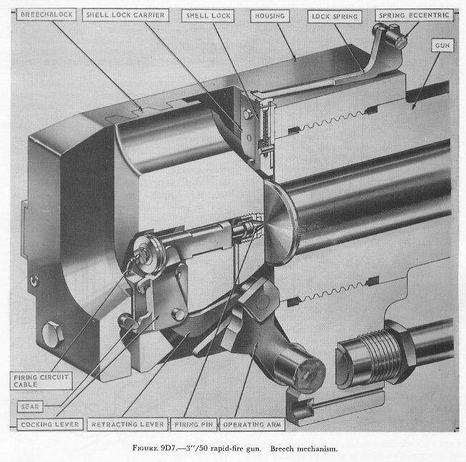 |
| 9D6. Shell lock The breech shell lock (fig. 9D7) functions to prevent a rammed cartridge from rebounding or backing out of the breech to foul the rising breechblock. It is a vertically sliding latch that rides in a slot in the shell-lock carrier on the face of the breech. The latch is moved upward during ramming and allows the round to pass into the bore. It is then moved down by action of the lock spring to trap the seated round. The rising breechblock pushes the shell-lock latch clear. It remains clear after firing until the extractors have moved the lip of the empty case past the shell lock, allowing extraction. |
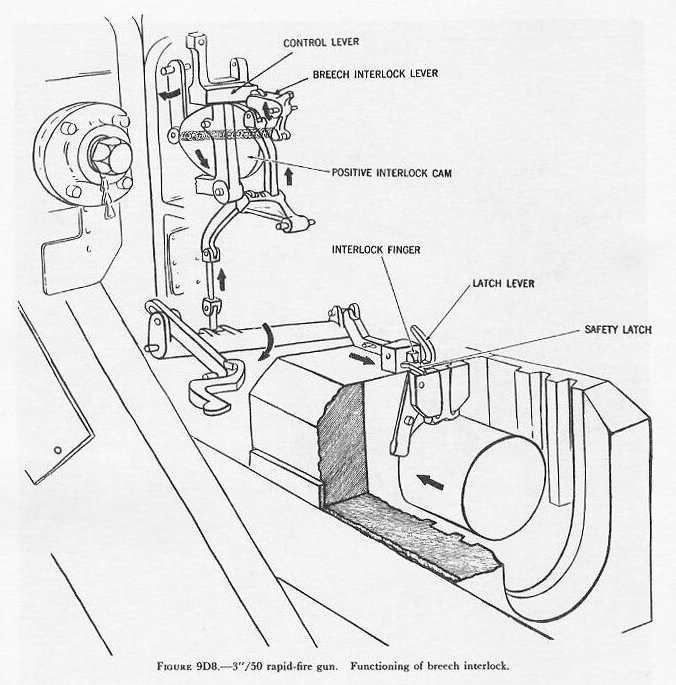 |
| 9D7. Breech interlock The breech interlock mechanism (fig. 9D8) is a system of mechanical linkages which function automatically to stop the loader from delivering another round to the breech whenever there is a round in the bore or the breechblock is up. The breech interlock latch lever, the first mechanism in the chain of linkages from the breech face to the loader control lever, is pivoted in the shell-lock carrier next to the shell lock and extends down the breech face, partially in front of the breech opening. When either a round is rammed or the block is raised, the latch lever is moved aside, actuating, through linkages, the loader control lever and stopping the loading cycle. 9D8. Firing mechanism The firing mechanism (fig. 9D7) consists of the following: 1. Breechblock firing-pin insulation. 2. Firing-pin assembly. 3. Firing-pin cocking mechanism and sear. The firing pin is a steel rod with a conical head that extends through the breechblock. It is similar to the 5ö/38 firing pin. It provides an electrical path for electrical firing and hammer action for percussion firing. By action of the cocking mechanism, the firing pin is cocked for percussion firing and positioned for electrical firing with each cycle of the breechblock. The cocking mechanism consists of the retracting lever and the cocking lever. The retracting lever moves the firing pin aft to keep it from shearing or fouling as the block lowers, and moves it forward into contact with the case electric primer when the block rises. The cocking lever holds the cocking sleeve aft against spring pressure during this up stroke (unless it is released by the sear if percussion-type firing is used). It should be understood that electrical firing is the normal firing method. Percussion firing, using a special short case with percussion-type primer, is employed for clearing-round action only. This short case is used only if a projectile has separated from the case and remains lodged in the gun while an attempt is being made to unload a round through the breech. Selection for percussion firing is made by setting an ELECTRIC-PERCUSSION lever near the left side plate of the gun. The firing circuit of this gun cannot be closed by the firing keys alone. The various electrical interlock switches of the loader control system, such as the TRAY UP switch, must also be closed to energize the firing circuit. Thus any dangerous malfunction of the loading cycle will cause the firing circuit as well as the loader control circuit to open. |
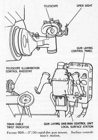 |
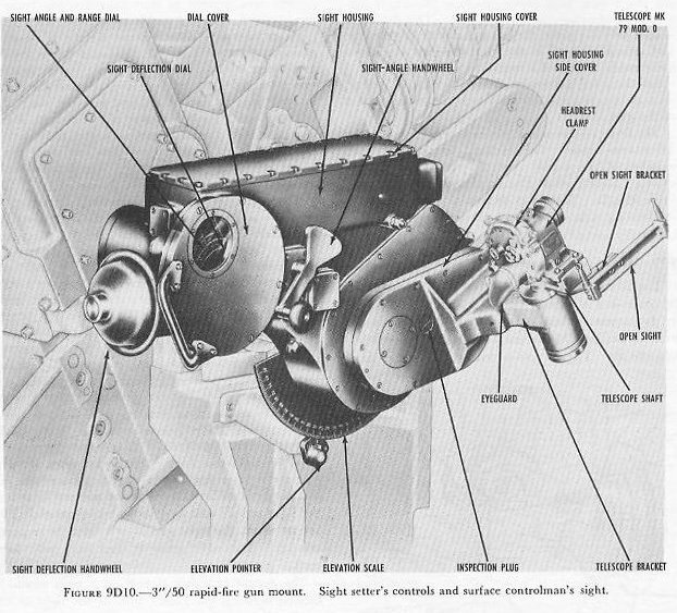
| 9D9. Mount control stations The mountĺs amplidyne electric power drives may be controlled in automatic from a director or in local at the mount. There is no manual control as such, only an auxiliary handcrank for securing or servicing the mount. These mounts feature a unique local control arrangement in that there are two types of local control, local AA and local surface. Each has a separate control station. Local surface is the right gun-laying station (fig. 9D1). Local AA is the left gun-laying station. When the gun-laying drive selection is local AA, the left gun layer controls the mount in both train and elevation, and fires the gun. The left gun layerĺs controls consist of a ring sight, a one-man gun-laying control unit with gun firing key in right hand grip, a fire cutout indicator, and a gun-laying emergency stop control. There is no sightsetting provision at this station. The right gun layer is responsible for starting the elevation and train drive, selecting the control station, laying and firing the guns when the drive selection is local surface, and observing correspondence between gun position and gun order signals. The right gun layerĺs controls consist of a telescope and open sight, a one-man gun-laying control panel, and a train cable-twist indicator (fig. 9D9). The gun-laying control panel, for a twin mount, contains a control-station selector switch, gun-firing cutout lights, power-on lights, correspondence-indicator meters to indicate correspondence between gun and mount position and the order signal, and power START and STOP buttons. Used in conjunction with the local surface station but requiring an additional operator, is the sight setterĺs station (fig. 9D10). It is located directly behind the right gun layer. The sight setter operator receives sight-setting orders via telephone from the director or other fire control station and sets them into the sight setterĺs unit by handwheel operation. This action offsets the right gun layerĺs sight the required amount. The sight setter is used only with local surface gun laying. The mount captainĺs station on a twin mount is located between the guns. It is to the right of the gun on a single mount. The mount captain is the supervising gunner and crew captain. His operations are directed via telephone by the control officer. He controls and directs the performance of both guns by his use of the mount captainĺs controls. In emergency he stops the firing of either or both guns. His panel of switches allows him to select the control station, switch to single or automatic fire, and select the gun or guns to fire. |
Other elements of his control panel are master push buttons for stopping either one or both of the loaders, power-drive emergency stop buttons, and various illuminating indicators to indicate the occurrence and location of malfunctions. The gun captainĺs firing key must be closed before the loaderĺs will function. The key has a latch to hold it in closed position when control of fire is to be at either left or right control station or at the director. |
 |
| 9D10. Ammunition The 3ö/50 gun fires fixed ammunition. A complete round is 34.74 inches long and weighs 24 pounds (the projectile, with fuze, weighs 13 pounds). Since neither the mount installation nor the associated fire control system includes provision for fuze setting, only VT-fuzed projectiles are used in AA fire. Base-fuzed and point-detonating fuzed projectiles for surface fire are also available. |
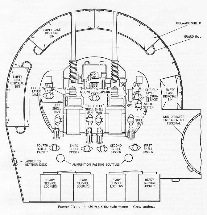 |
| 9D11. Personnel The personnel arrangement of a 3ö/50 rapid-fire twin mount is shown in figure 9D11. The normal crew is composed of 11 men, as follows: a mount captain, 2 control-station men, 4 shellmen, and 4 shell passers. (One control-station man controls the mount in local surface, the other in local AA.) An additional crew member, a sight setter, is required in local surface control. The shellmen transfer ammunition from the gun carriage racks to the right and left sides of the hopper of each gun. The shell passers keep the carriage racks, called magazines, supplied with ammunition from a ready-service locker or hand-passing scuttles leading up from the handling rooms. The handling rooms are supplied by dredger hoist from the shipĺs magazines. The number of passers may vary, depending upon the arrangement of ready-service lockers and passing scuttles. |