| NAVAL ORDNANCE AND GUNNERY, VOLUME 1 CHAPTER 9 AUTOMATIC WEAPONS |
| HOME INDEX Chapter 9 Automatic Weapons A. Introduction B. 20-mm aircraft gun C. 40-mm guns and mounts D. 3"/50 rapid-fire guns and mounts |
| B. 20-mm Aircraft Gun 9B1. The general problem of aviation gunnery Because aircraft speeds are high and constantly tend to become higher, actual firing time in any attack is limited to seconds. For this reason it is essential that rate of fire be rapid, so that there is reasonable probability of scoring enough hits to do effective damage. High projectile velocity is also desirable, to reduce time of flight and thereby minimize the effect of many variables which tend to detract from accuracy. It must also be remembered that performance of the airplane itself is a factor in the effective employment of the plane’s guns. Recognition of targets is one of the most critical items in air combat, because it is the key to making initial estimates of range, speed, and mission. A common error in aerial gunnery is to open fire before the target comes within range, and to continue fire when the target is beyond effective range. In fact, the general problems of aircraft gunnery can be reduced to questions of who, where, and when. “Who” refers to the problem of whether a potential target is friend or foe, and if foe, what the type of plane may be. “Where” is the problem of target location relative to the gun, which in modern installations may be solved or largely solved by automatic means. “When” is the problem of when to open and cease fire to provide maximum probability of obtaining hits, yet maintain necessary conservation of a limited ammunition supply. 9B2. Types of aircraft guns and installations Aircraft guns incorporate certain modifications of conventional gun structures to reduce weight and length, and generally to make them adaptable to aircraft installation. Guns as small as caliber .30 machine guns, and as large as 75-mm guns, have been installed in military planes. The aviation gun in current Navy use is the 20-mm automatic gun, but the caliber .50 machine gun was the one most extensively used in Navy planes throughout World War II. However, the latter weapon seems destined to have little potential significance in future aircraft installations. Aircraft guns may be installed on either fixed or free mounts. Fixed guns are rigidly attached in the forward part of the plane, including leading wing edges, and may be trained or elevated only by maneuvering the plane. They are, of course, forwardfiring guns. Free mounts, on the other hand, provide for train and elevation in limited arcs. The British first used airplane turrets mounting flexible guns in battle during World War II. The modern aircraft turret is a self-contained mechanized unit, consisting of an enclosure housing the gunner, guns, ammunition, power drives in train and elevation, armor plate, and other accessories. Such an installation provides many advantages: the angle of fire is increased; movement of guns in elevation and train against the force of the slipstream is facilitated; larger guns can be utilized more readily, the gunner is protected; and, in general, a more adequate defense can be realized in the case of larger, slower aircraft. In addition, a fire control system may be installed to provide local and remote control. |
 |
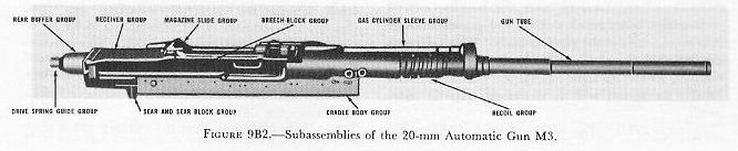 |
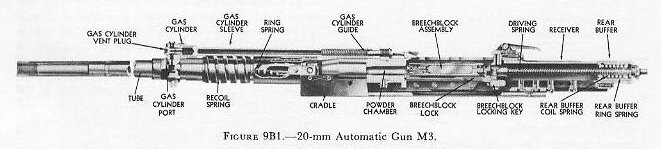
| 9B3. Development of the 20-mm Gun M3 During the interim between World War I and World War II, both the Germans and the Japanese developed 20-mm guns for aircraft installation, and during World War II the Germans installed as many as six of these guns in some planes. Our own development of a 20-mm gun was initiated in 1937, and speeded up when the European conflict began. Since its inception this gun has undergone two major changes, each incorporating some improvement in design and operating characteristics. The end product of this technological advance is the 20-mm Aircraft Gun M3. Figures 9B1 and 9B2 show this gun. 9B4. General description The 20-mm Aircraft Automatic Gun M3 is an air-cooled weapon weighing approximately 100 pounds, and is capable of firing up to 800 rounds of ammunition per minute at an initial velocity of 2,730 feet per second. Operating with the gun is a feed mechanism mounted on top of the gun proper. Rounds of ammunition are fed into the gun from a disintegrating link belt. A charger retracts the breechblock initially and cocks the gun, or can remove a round from the chamber. Firing is done by an electric trigger, which fires the 20-mm Automatic Gun M3 by remote control. Each of these units will be discussed below. 9B5. Principles of functioning Power to keep the gun operating automatically comes from the energy released each time a round is fired. This energy is utilized in three ways: 1. When the round is fired, some of the ammunition propellent gas goes through a small hole drilled in the gun barrel to act on the gun components and unlock the breech block. This is called gas operation. 2. The expanding gas remaining in the gun barrel pushes the breech locking and closing components to the rear. This is called blowback. 3. Firing the gun causes some of the gun components to recoil. The energy of recoil compresses springs of some of the gun components. The expansion of these springs causes these components to counterrecoil and return the gun to battery. Recoil and counterrecoil activate the feed mechanism which supplies ammunition to the gun. Since the 20-mm M3 gun utilizes all these sources of power, it is classified as a combination gas-operated, blowback, and recoil weapon. The functioning of the main parts of the gun in the entire automatic action is described under the following heads: 1. Recoil mechanism. 2. Receiver. 3. Breechblock. 4. Driving-spring assembly. 5. Gas mechanism. 9B6. Recoil mechanism The function of the recoil mechanism is to cushion the impact of recoil and return the gun to battery. The recoil mechanism consists of a recoil spring and a recoil housing assembly. Recoil spring. The recoil spring is a heavy, flat, helical (or coil) spring which surrounds a portion of the gun barrel slightly forward of the chamber. The front end of the recoil spring seats against a bracket which is directly attached to the gun barrel and recoils with it. The after end of the recoil spring rests against the recoil housing assembly, a nonrecoiling part. Recoil housing assembly. The recoil housing assembly consists of two main parts: a hollow tube, or sleeve, and a separate spring called the ring spring, which fits inside the sleeve. The sleeve is a cylindrical steel tube that surrounds the gun barrel abaft the recoil spring. It is secured to the stationary mounting assembly of the gun and does not recoil. As the gun recoils, the gun barrel moves rearward, attempting to carry the recoil spring with it. The recoil spring bears against the ring spring inside the sleeve of the recoil housing assembly. The stationary sleeve forces both springs to compress, stopping the recoil movement. Recovery of the springs initiates counterrecoil and returns the gun to the battery position. 9B7. Receiver The receiver is the component of the gun assembly that mounts the barrel and houses the breechblock and driving-spring assembly. It consists of three main components: the receiver body, the breechblock-locking key, and the receiver slides. Receiver body. The receiver body is a hollow rectangle, partially open at the top and bottom and fully open at the rear. A large opening in the front end of the receiver body is threaded to receive the gun barrel. Since the gun barrel is directly attached to the receiver, the receiver is a recoiling part. Breechblock-locking key. In approximately the midpoint of the receiver, near the bottom, a solid rectangular breechblock-locking key passes through slots on the sides of the receiver body. This key keeps the breechblock, which slides back and forth in the receiver, locked up tight against the chamber during firing. Its action will be described later in more detail. Receiver slides. The two receiver slides are metal strips bolted inside the front of the receiver body, one on each side. They support the breechblock when it is in the front of the receiver body, and aid in locking the breechblock in firing position. Cam surfaces at the rear of the slides engage corresponding cam surfaces on the breechblock lock (a hinged arm) of the breechblock mechanism as it moves forward in the receiver. The resulting action forces the lock downward into a notch in the breechblock-locking key and locks the breechblock in firing position. |
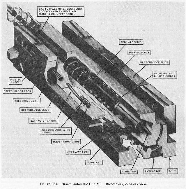 |
| 9B8. Breechblock The breechblock moves forward and backward inside the receiver body. On the forward movement it takes the ammunition cartridge from the mouth of the feed mechanism, carries it into the chamber, and fires the round. On its return stroke, the breechblock carries the empty cartridge case to the ejector. Figure 9B3 is a sectional view of the breechblock. The breechblock consists of the bolt, the breech-block lock, two breechblock slides, a firing pin, and an extractor. See figure 9B3. Bolt. The bolt is the main component of the breech-block. It helps carry the cartridge to the gun-barrel chamber and closes the breech end of the barrel. It also houses the firing pin and supports the breech-block slides, the extractor, and the breechblock lock. The firing pin and driving spring are inside the longitudinal tunnel of the bolt. The tip of the firing pin protrudes through a small tapered hole in the front of the bolt. The bolt’s front face is recessed to accommodate the base of the cartridge case. Flanges along the lower edges of the bolt guide the breechblock slides. The bottom of the bolt is recessed at the rear to receive the breechblock lock, and at the front to accommodate the extractor. The extractor is attached to the bolt by the extractor pin and a cylindrical strut-type spring which forces the forward end of the extractor toward the face of the bolt. Breechblock lock. The breechblock lock seats on the breechblock-locking key. It locks the breechblock in battery while the round is fired. The breechblock lock is a flat plate with cams projecting from each side of its top surface. When the breechblock moves forward, these cams engage the receiver slides and force the breechblock lock downward against the breechblock-locking key. The rounded forward edge of the breechblock lock fits into a mating recess in the breechblock bolt. This arrangement provides a hinge action between the lock and the bolt. The protruding shoulders on top of the lock move up into the notched section of the breechblock’ slides when the slides are retracted. Breechblock slides. Two breechblock slides serve to guide and support the bolt in the receiver. These slides are shorter than the bolt, and slide forward and backward on the flanges along the lower edge of the bolt. The 2 slides, 1 on each side of the bolt, are keyed together by the slide key, a flat, rectangular piece of metal with rounded edges, which extends through a slot in the bolt. This slot is elongated to allow the slide key to move forward and backward during the locking and unlocking action of the breechblock. The slide key also mates with a recess in the firing pin, so that the breechblock slides and firing pin operate together. The bottom edges, near the rear of the breechblock slides, have notched recesses cut in them to accommodate the raised shoulders of the breechblock lock when the breechblock is unlocked. It will be remembered that the breechblock lock, hinged to the bolt, is cammed down by the receiver slides and engages with the breechblock-locking key as the breechblock moves forward just prior to firing. At this time the breechblock is in its full forward position in the receiver, and the breech end of the gun barrel is closed and locked. This is the firing position. The breechblock lock cannot move back up into the notched recesses in the breechblock slides, because the slides continue to travel forward slightly after the lock is cammed down. The rear ends of the breech-block slides, abaft the notched recess, rest on top of the raised shoulders of the breechblock lock and prevent it from rising. |
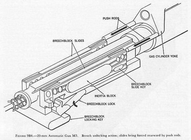 |
| When the breechblock is unlocked by the gas mechanism after firing, the breechblock slides, are pushed backward by push rods, which also compress springs inside the slides. See figure 9B4. The forward inner notched surface of the slides catches the raised shoulders of the breechblock lock and forces it up and free from the breechblock-locking key. The breechblock lock moves back up into the recess in the slides and prevents the slides from moving with respect to the bolt. The slides, however, have stored energy in the compressed springs located inside them. When the breechblock lock is cammed down, freeing the slides to move, the springs expand and push the slides forward. Firing pin. The firing pin strikes the round in the chamber of the gun barrel and fires the round. The firing pin is cylindrical, with a tapered tip in front and a machined slot approximately in the center of the body. The slot allows the firing pin to ride on the slide key which extends between the two breechblock slides. As the breechblock moves to battery position, the breechblock slides and slide key carry the firing pin forward, causing its tip to protrude from the breechblock bolt and fire the round. After firing, the breechblock slides and slide key move rearward and retract the firing pin. Extractor. The extractor grips the round as it enters the chamber, holds the round during firing, and draws the empty case rearward as the breechblock is blown back by the expanding gases after firing. Ejector prongs fastened to a nonrecoiling part of the gun assembly strike the top of the cartridge case as it moves rearward. The extractor and empty case are pivoted downward, and the case drops through a hole in the bottom of the receiver and out of the gun. The extractor spring forces the extractor upward to the position where it grips the next round. 9B9. Driving-spring assembly When initial recoil movement begins, the barrel, receiver, and breechblock all move rearward together. Shortly after recoil begins, however, the breechblock is unlocked from the receiver. The expanding gases in the chamber, acting against the face of the breech-block, blow it back faster than the receiver and barrel are recoiling. The recoil mechanism, discussed earlier, absorbs the force of recoil and initiates counterrecoil. The receiver will not carry the breechblock forward with it in counterrecoil, since the two are not locked together as at the moment of firing. It is the function of the driving-spring assembly to make the breechblock counterrecoil- and return to battery position. The main parts of the driving-spring assembly are the driving-spring plunger and the driving spring. Driving-spring plunger. The forward end of the driving-spring plunger is attached to the base of the firing pin. The after end is attached to the rearmost component of the gun assembly, the rear buffer, which in turn is attached to the rear of the receiver. The plunger telescopes as the breechblock is blown back. Driving spring. The driving spring surrounds the plunger and is compressed as the breechblock moves to the rear. It is the recovery of the driving spring that drives the breechblock forward to strip ‘a round out of the feed mechanism and chamber it ready to be fired by the firing pin. 9B10. Gas mechanism The gas mechanism unlocks the breechblock and retracts the firing pin when the gun has fired. The gas mechanism consists of a cylinder which mounts on top of the gun, covering a small hole drilled in the top of the barrel; a piston and rod which move rearward in the cylinder against spring pressure; and two push rods which are forced rearward by an extension of the piston rod, called the yoke (fig. 9B4). As the gun is fired, the projectile moves forward, uncovering the small hole, or port, in the top of the barrel. Some of the expanding propellent gas escapes through the port into the cylinder, where it exerts pressure on a piston and rod, forcing the rod rearward against spring pressure. The yoke on the piston rod pushes the two push rods, which are free to move back and forth in longitudinal holes drilled in the front of the receiver body. In turn, the two push rods, when forced rearward by the yoke, force the breechblock slides back, retracting the firing pin and unlocking the breechblock. The propellent gases, still inside the barrel, force the breechblock rapidly to the rear. (This is blowback.) As the gas pressure lessens in the gun barrel and the gas cylinder, spring pressure in the cylinder gradually forces the piston rod and yoke forward to the position where they are ready for another cycle. The push rods slide forward freely when struck by the counter-recoiling breechblock slides. 9B11. Cyclic action In an automatic gun like the 20-mm Aircraft Automatic Gun M3, the firing of a round furnishes the energy to carry on the cyclic functioning of the gun to fire succeeding rounds. The sequence of cyclic actions is: 1. Gun fires and recoils. 2. Breechblock unlocks. 3. Breech opens and fired case is ejected. 4. Gun counterrecoils and driving spring drives breechblock forward (picking up a new round). 5. Breechblock locks. 6. Gun fires and recoils. 9B12. Gun fires and recoils When the round is fired, the gun barrel, receiver, and breechblock recoil. The gun barrel carries rearward the recoil spring which surrounds it. The recoil spring contacts the ring spring inside the stationary sleeve of the recoil housing assembly, compressing both springs and stopping recoil movement. 9B13. Breechblock unlocks At the moment of firing, the breechblock is held against the breech of the gun barrel by the breechblock lock resting against the breechblock-locking key. The breechblock lock slides prevent the breechblock lock from disengaging until after firing. The action of the gas mechanism unlocks the breech as shown in figure 9B4. Propellent gases enter the gas cylinder through the small hole in the gun barrel. Gas pressure forces the piston rod and yoke aft. The yoke, through the two push rods, forces the breech-block slides rearward. The breechblock slides are connected by the breechblock-slide key, which actuates the firing pin. The firing pin is notched to fit over the breechblock-slide key. Therefore, as the breech-block slides move rearward, the breechblock-slide key retracts the firing pin. The notched sections at the rear of the breechblock slides engage the protruding shoulders of the breechblock lock, forcing the lock clear of the breechblock-locking key, and unlocking the breechblock. 9B14. Breech opens and fired case is ejected After unlocking, blowback starts the breechblock to the rear. As gas pressure in the gun barrel drops, spring action in the gas cylinder returns the gas mechanism components to their original position. The breechblock and extractor move backward until the tip of the fired case strikes the stationary ejector prongs, pivoting the empty case out of a hole in the bottom of the receiver and out of the gun. 9B15. Gun counterrecoils and driving spring drives breechblock forward The recoil spring and ring spring, which were compressed during recoil, now expand and start the receiver and gun barrel forward in counterrecoil. The breechblock, when it was blown back in the receiver, compressed the driving spring in the bolt. Recovery of the driving spring sends the breechblock forward toward firing position, where it picks up a new round of ammunition from the feed mechanism. 9B16. Breechblock locks As the breechblock moves forward in the receiver, projecting cams on the breechblock lock engage camming surfaces on the receiver slides, forcing the lock to rotate downward. The breechblock lock seats against the breechblock-locking key in the receiver, and is held by the rear lower surface of the breech-block slides. Simultaneously, the breechblock bolt reaches the end of its forward motion and chambers the cartridge. The slide springs, combined with the momentum of the driving spring, cause the breech-block slides and breechblocks slide key to continue forward after the bolt has stopped. 9B17. Gun fires and recoils The firing pin is carried forward by the breech-block-slide key, and by the expanding driving spring. The firing pin strikes the cartridge primer and fires the round. This cycle repeats until the trigger is released or the ammunition is expended. 9B18. Feed mechanism The feed mechanism used with the 20-mm Aircraft Automatic Gun M3 is designated the AN-M2 feed mechanism. It is designed to feed up to 800 rounds of ammunition per minute into the gun. The linear movement of gun components in recoil and counter-recoil is transformed to rotary motion by mechanical means in the feed mechanism. This rotary motion winds coil springs which drive a set of starwheels. The starwheels are 9-toothed sprockets contoured to fit between the cartridge cases in the ammunition belt. As the starwheel housing rotates, the two starwheels engage the incoming rounds, drawing them into the feed mechanism. Once inside, stripper cams strip off the detachable links which hold the rounds together in belts. The cartridge is then aligned with the mouth of the feed mechanism. The extractor grips it and rams it into the gun chamber. 9B19. Charger A charger is used to retract the breechblock and cock the gun, or to remove a round from the chamber. A lug on the breechblock slide extends through a long slot in the receiver. This lug is engaged by the charger, which draws the entire breechblock assembly to the rear until it reaches the cocked position. The breechblock is held in this position by the trigger mechanism. Charges may be either manually, hydraulically, or pneumatically operated. 9B20. Electric trigger The trigger in the pilot’s compartment and the mechanism which actuates firing at the gun are connected electrically. The mechanism that holds the breechblock in the rear of the receiver and prevents firing is the sear. The sear mechanism is fastened to the underside of the receiver. The sear itself is a hooked arm which engages with a recess in the bottom of the breechblock lock, preventing it from moving forward. The other main part of the sear mechanism is a solenoid assembly. Pressing the trigger causes the solenoid assembly to draw the sear out of the path of the breechblock. When the circuit is opened, a spring forces the sear upward again, where it engages the breechblock lock. |