Part F: Turret Fire Control Equipment
20F1. General
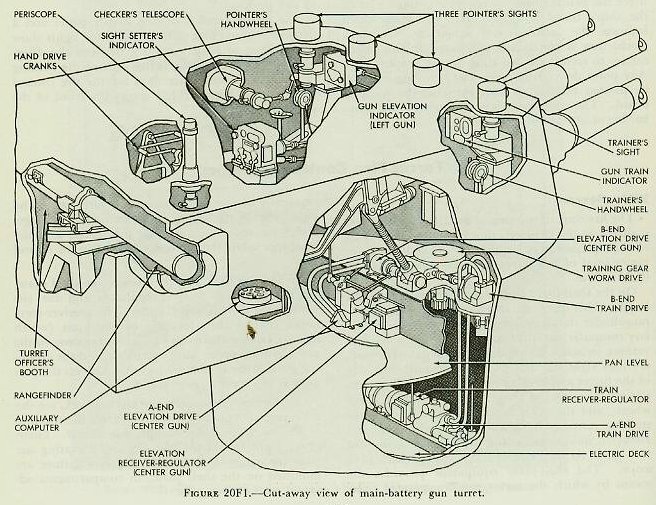
The fire control equipment installed in the turret is shown in the cut-away view of
figure 20F1. Part of the equipment is located on the shelf plate, or upper level of the turret, and the rest on the two decks below.
On the shelf plate at the rear is the turret officer’s booth. This space contains the rangefinder and the rangefinder stabilizer, the spotter’s periscope, auxiliary computer, multiple turret train indicators, and various switches and indicating lights. Forward, are four sight stations, one on each outboard side of the turret and two between the guns. The right station contains the trainer’s periscope and hand-wheels, and the train indicator. The other three stations contain the periscopes, handwheels, and elevation indicators for the three pointers, one for each gun. At the extreme left is the checker’s periscope. The shelf-plate equipment provides the means by which the turret can be operated independently of the rangekeeper and directors. The sights enable the target to be located; the range-finder measures the range to the target; arid the computer solves the fire control problem for Vs and Ds.
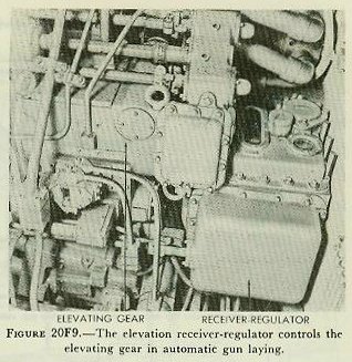
On the pan floor, one deck below the shelf plate, are the elevation receiver-regulators and the elevating gear A-ends and B-ends. The receiver-regulators control the elevation of the guns (which operate independently in elevation) response to the gun elevation order (auto and local), and the elevating gears actually move the guns. Also on the pan floor is the training-gear B-end.
On the next lower deck, the electric deck, are the train receiver-regulator, which controls the training of the turret, and the training-gear A-end. Emergency hand cranks for training and elevating the guns manually in the event of power failure are mounted on the shelf plate, in compartments adjacent to the wing guns.
20F2. Rangefinder
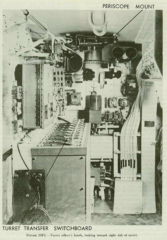
The rangefinder passes through the turret officer’s booth in back of the beam at the upper right of
figure 20F2. Turrets 2 and 3 are equipped with rangefinders of the erect-image stereoscopic type and are capable of measuring ranges from 2,500 to 50,000 yards. The base length is 26 feet 6 inches, and the magnification is 25 diameters. The range-finder in turret 1 is of the erect-image, coincidence type, with the same base length and magnification.
Sighting through the main eyepiece, the range-finder operator adjusts the measuring knob to keep the wander mark on the target in the stereoscopic type of rangefinder, or to match the two images in the coincidence type. The operator then presses the switch in the center of the measuring knob, which sends an electrical signal designating the range to the rangekeeper. Range may also be read from the range scale and transmitted by phone (JW circuit) to the rangekeeper operator. Besides the main eyepiece there is a rangefinder trainer’s eyepiece, used for locating and centering the target in the main instrument field.
The rangefinder stand supports the rangefinder in two saddle bearings, which permit the range-finder tube to be rotated through 30 degrees. The stand also permits deflection of the rangefinder 5°30’ left or right of the line of the gun bore, to nullify the deflection of the guns from the line of sight.
The rangefinder is stabilized in level-that is, its line of sight is held horizontal as the ship rolls- either by means of a hand lever or by the rangefinder stabilizer. The latter device consists of a gyroscope, which activates an electric-hydraulic follow-up system to keep the rangefinder level. A clutch handle is provided to shift from hand to automatic stabilizing.
20F3. Periscope
Figure 20F2 shows the periscope mounted in the roof of the turret, which serves for general lookout purposes; for picking up targets; for estimating their range, course, and speed; and for spotting the fall of shells.
20F4. Auxiliary computer
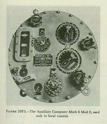
The Computer Mark 6 shown in
figure 20F3 is a standby instrument intended for use only when the turret is isolated by casualties. It is located at the right side of the turret officer’s booth and operates without mechanical or electrical inputs to compute Vs and Ds. It will not be described here.
Because some of the refinements of calculation found in Rangekeeper Mark 8 are omitted from the design of the auxiliary computer for compactness and to permit the use of the computer independently of the major control systems, the solution obtained with it is not as accurate as with the more complex instrument.
20F5. Multiple turret train indicator
The turret officers’ booth contains an MTTI similar to those in the plotting room and fire control stations. Turrets 1 and 2 each contain a train indicator showing turret train and gun train order for turrets 1 and 2; turret 3 contains an indicator showing such data for own turret only.
20F6. Eight-inch sight
The turret sight consists of the trainer’s, checker’s, and the three pointers’ periscopes and the shafting which connects them with the sight setter’s indicator and the gun attachments. The sights are used to aim the guns in LOCAL, and to check the aim in other methods of gun laying.
As the trainer trains the turret to bring the vertical crossline on the target, and the pointers elevate the guns to bring the horizontal crosslines on the target, the gun bores are deflected both horizontally and vertically from the line of sight according to the sight angle and sight deflection set in by the sight setter.
The line of sight of all the sight telescopes may be deflected 110 mils right or 90 mils left of the gun axis, and the pointers’ and checker’s telescopes may be elevated 1° above or depressed 41° below this axis. Stops on the foot treadle and hand lever of the trainer’s sight permit 18° movement above and below a plane parallel to the roller path of the turret.
As previously mentioned, the turret sight is used primarily for positioning the turret guns in local gun laying. However, in those methods of gun laying where the sight is not directly employed, the telescopes are continuously positioned by the combined action of the sight setter and gun elevation response, so that they may be used for checking purposes, and so that they may be in constant readiness for change-over to local control if necessary.
20F7. Sight setter’s indicator
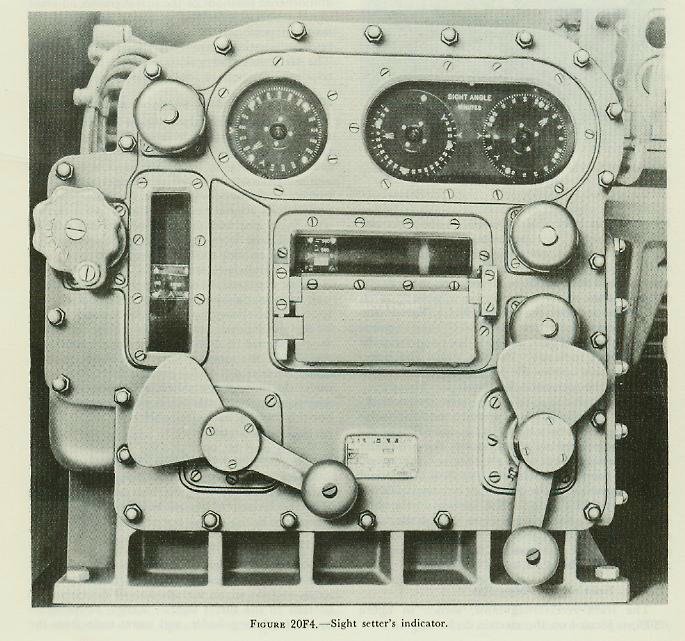
The sight setter’s indicator, shown in
figure 20F4, is located abaft the center pointer’s station in each turret and serves as a range, sight-angle, and sight-deflection indicator. The sight setter’s indicator receives two electrical inputs: sight angle and sight deflection. By turning cranks on the front of the instrument to match the outer dial with the inner electrical dials, these quantities are transmitted mechanically to the sights. Sight angle is also transmitted by shafting to the gun elevation indicators and receiver-regulators, where it is used in the erosion-correction mechanisms.
The sight setter’s indicator contains a parallax range scale and crank, and a range scale. By turning the parallax-range crank to set in the range read from the range scale, the sight setter transmits parallax range to the train indicator and the train receiver-regulator, where it is used in computing the parallax correction. Since sight angle is a function of range for a given muzzle velocity, it can be converted to range. This is done by the range scale, which is driven according to the sight angle set in the instrument, but which is graduated to read range.
The sight setter’s indicator is used to set the sights in all methods of gun laying and of turret drive. In addition, it supplies mechanical inputs of sight angle and parallax range respectively to the elevating and training equipment, for the purposes noted, in both automatic and indicator gun laying.
20F8. Training equipment
The training equipment consists of the trainer’s handwheels, the gun train indicator, the train receiver-regulator, the training speed-gear A-end and B-end, and accessory equipment.
The turret is trained by means of the training speed gear controlled by the train receiver-regulator or the trainer’s handwheels.
The trainer’s handwheels may be connected by means of a clutch to the tilting plate of the training-gear A-end, or to the receiver-regulator. The trainer operates his handwheels either to bring his vertical crossline on the target (in local gun laying) or to match the dials of the gun train indicator (in indicator gun laying).
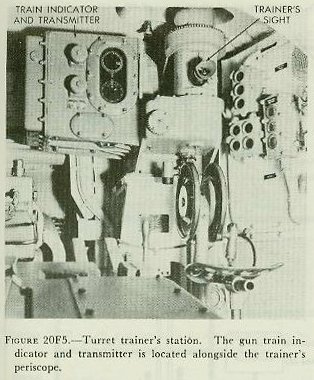
20F9. Gun train indicator and transmitter
The gun train indicator, shown in
figure 20F5, is located at the trainer’s station on the right side of the turret. The instrument receives gun train orders on synchro receivers. It is used in indicator gun laying to guide the trainer in operating his handwheels so that these orders are carried out. One synchro receiver operates a zero-reader dial; the other a follow-the-pointer dial. The instrument mechanically receives turret train response from the training gear, and parallax range from the sight setter’s indicator. Parallax range and turret train response operate the parallax corrector, which computes the correction for parallax. This correction is introduced into turret train response by means of a differential to produce modified-turret train response, which operates the outer dial of the follow-the-pointer dials, and restores the zero-reader dial to zero. Turret train response is displayed on dials for comparison with the electrical order dials, and is transmitted electrically by synchro transmitters to the MTTI’s in various stations in the ship. In automatic gun laying the gun train indicator is not used to control the turret, but still indicates gun train order and modified turret train response, and transmits the latter to the MTTI’s.
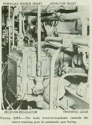
20F10. Train receiver-regulator
The train receiver-regulator, shown in
figure 20F6, is located on the electric deck.
It controls the training gear in accordance with an electric gun train order. The instrument has three inputs: gun train order (received electrically from the plotting room or auxiliary switchboard, or mechanically from the trainer’s handwheels, depending on the method of gun laying employed); parallax range, received mechanically from the sight setter’s indicator; and turret train response, received mechanically from the training gear. Within the regulator, turret train response is corrected for horizontal parallax and matched with gun train order. The difference between the actual and ordered positions of the turret creates an error signal which is amplified and used to control the training speed gear in such a manner that the turret is automatically trained to the ordered position. The train receiver-regulator operates normally in response to remote or local signals.
20F11. Training speed gear
The turret is trained by the hydraulic training gear, which consists of a motor-driven pump (A-end) and a hydraulic motor (B-end). Part of the gear can be seen in
figure 20F6. The hydraulic motor drives a pinion which engages with a stationary rack mounted on the barbette. As the pinion rolls around this rack, the turret is carried with it. Speed and direction of rotation depend upon oil flow from the A-end, which in turn is controlled by the train receiver-regulator or mechanical handwheel drive.
In the event of power failure, the turret may be trained by manual power. The training-gear A-end is connected through a clutch to two handcranks located on the shelf plate. By engaging this clutch the A-end may be driven by turning the cranks instead of by the motor. This form of operation is called manual drive. In manual drive, the training of the turret is controlled by the trainer’s hand-wheels in the same manner as when power is used, but the training rate attainable is, as might be expected, much slower.
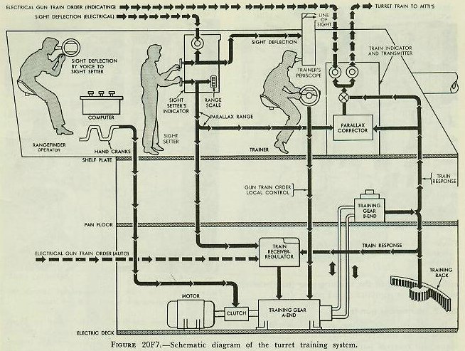
20F12. Operation of training equipment
Figure 20F7 is a functional diagram of the turret training system, showing the instruments described above. The path of quantities in the various methods of gun laying can be traced on this diagram.
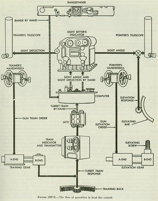
20F13. Local gun laying
Local gun laying is used in local fire control. The target is located by means of the turret periscope, and the turret is trained until the target can be seen in the turret sights. Range, as measured by the local rangefinder, and turret train from the MTTI are set into the computer as hand inputs, and with these data, and the other hand inputs, a value of sight deflection is computed. This computed sight deflection is sent to the sight setter by phone, and he cranks the value into his sight setter’s indicator, thus deflecting the pointer’s and trainer’s sights. The trainer operates his hand-wheels to keep his vertical crosslines on the target, and thus deflects the gun by the amount of the deflection angle turned into his sight. In local fire control no horizontal parallax correction to turret train is necessary.
In primary, secondary, and auxiliary fire control the turret may be trained in either indicator or automatic gun laying.
20F14. Indicator gun laying
In indicator gun laying, turret train response is corrected for parallax in the gun train indicator and compared with the gun train order on the dials of that instrument. Observing the dials, the trainer trains the turret in accordance with the orders received. Training of the turret is accomplished by means of the trainer’s handwheels, which control either the A-end of the training gear (hand drive) or the receiver-regulator (local power drive).
20F15. Automatic gun laying
In automatic gun laying, gun train order is received by the train receiver-regulator. This instrument also receives parallax range from the sight setter’s indicator and turret train response from the B-end of the training gear. Combining these inputs, the receiver-regulator automatically controls the A-end of the training gear so as to bring the turret to the ordered position. In automatic gun laying the gun train indicator transmits corrected turret train to the multiple turret train indicators throughout the system.
20F16. Elevating equipment
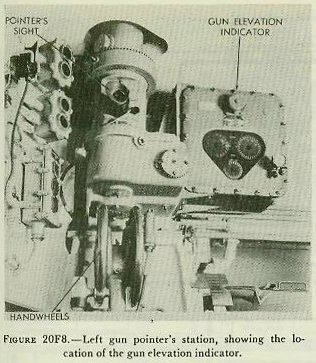
The elevating equipment is similar in fundamental principles and operation to the training equipment. It consists of the pointers’ handwheels, gun elevation indicators, elevation receiver-regulators, and the elevating speed-gear A-ends and B-ends. Each of the guns is elevated independently by its elevating gear, which is controlled either by the elevation receiver-regulator or by the pointers’ handwheels, depending on the method of gun laying employed. The handwheels may be connected through a clutch to the tilting plate of the elevating gear A-end, or to the receiver-regulator. The pointer operates his handwheels either to bring the horizontal crossline of his telescope on the target, or to match dials on the gun elevation indicator.
Figure 20F8 shows a view of, the left pointer’s station.
20F17. Gun elevation indicator
The gun elevation indicator functions in a manner similar to the gun train indicator. One of these is shown in
figure 20F8 at the left pointer’s station. In indicator gun laying the gun elevation indicator receives gun elevation order electrically and gun elevation response mechanically. These values are indicated on the zero-reader and follow-the-pointer dials and are used by the pointer in elevating the gun in follow-the-pointer operation.
Before gun elevation response is compared with the order, two corrections are made within the indicator to the response signal. These are (1) rollerpath tilt correction, and (2) erosion correction.
Roller-path tilt correction compensates for inclination of the turret’s roller path plane with respect to the ship’s reference plane for any angle of train of the turret. This correction varies with the position of the turret in train and with the inclination of the roller path. The inclination of the roller path is determined when the battery is aligned, and is set into the roller-path tilt mechanism by screw-driver adjustment. Train is received from the training gear. A computation based upon two inputs produces roller-path tilt correction for the particular train angle.
Erosion correction compensates for the reduced initial velocity of the projectile due to the erosion of the gun barrel as successive charges are fired. The effect of gun erosion on the trajectory varies with the range, which is a function of sight angle and the initial velocity of the projectile. The erosion corrector thus receives two inputs: sight angle, which provides the range function, and a hand input to account for the velocity loss. The usual practice is to put an initial velocity setting into the rangekeeper in Plot, or into the auxiliary computer in the fire control station, equal to that for the least eroded gun in the battery. A value of initial velocity loss, equivalent to the difference between the velocity set into the rangekeeper or computer, and the actual velocity obtained in the individual gun, is then set into each gun elevation indicator by means of the velocity-loss knob. A velocity-loss dial is provided to enable the operator to read the value of velocity loss introduced. Erosion correction and roller-path tilt correction are added (algebraically) to gun elevation response to produce modified gun elevation.
Summarizing, the inputs to the instrument are: Gun elevation orders, electrical; turret train, for the roller-path tilt correction; sight angle and velocity loss for the erosion corrections, and elevation response from the gun elevation attachment.
20F18. Elevation receiver-regulator
The elevation receiver-regulators control the elevating gears in accordance with gun elevation order. This order comes from the plotting-room switchboard or auxiliary switchboard, or from the pointer’s handwheels. One of these instruments is shown in
figure 20F9 located on the pan floor, beside the elevation A-end.
The elevation receiver-regulator, like the train receiver-regulator, is an electric-hydraulic follow-up device. It controls the A-end of the elevating gear. The unit has correction mechanisms to correct gun elevation response for roller-path tilt and erosion, and to compensate for the non-linear relationship between elevating-screw rotation and gun elevation. The first two corrections are the same as those made in the gun elevation indicator. The receiver-regulator has a velocity-loss knob and dial, by means of which velocity loss may be set into it, in a manner similar to that for the elevation indicator. It also receives sight angle from the sight setter’s indicator for computing erosion correction and turret train response from the training speed-gear B-end for computing roller-path tilt correction.
The elevating-screw correction compensates for the disproportionality between rotations of the elevating-screw nut and rotation of the gun about its trunnions. It should be noted that this correction is not necessary in the gun elevation indicator, because the elevation response input to this instrument is driven from a gear segment fastened to the gun, instead of from the elevating-screw drive; hence the proportionality of gun movement and response is constant for all gun elevations.
Gun elevation response, when corrected, is compared with gun elevation order, the difference between the two producing an error signal. This error signal controls the A-end of the elevating gear in such a way as to drive the gun to the ordered position.
A control selector at each pointer’s station is connected to the receiver-regulator by shafting. When thrown to LOAD, the selector positions hydraulic valves so as to bring the gun rapidly to the loading position after it has been fired. An auxiliary selector at the pointer’s station can be positioned to transfer loading control to the gun captain, which is the normal procedure. The gun captain may then exercise control by means of his ready switch. Return of the pointer’s selector to AUTO, or of the gun captain’s switch to READY, causes the receiver-regulator to reposition the gun at the existing value of gun elevation order.
20F19. Elevating gear
Each gun is elevated by an elevating screw which travels through a nut rotated by the B-end of the elevating gear. Part of an A-end may be seen in
figure 20F9. The gear consists of a hydraulic pump and motor similar to the training gear, and is controlled in the same way.
In manual drive, the A-end of the elevating gear may be connected, through a clutch, to the same hand cranks used for the training gear. The same clutch disconnects the electric motor. In manual drive, elevation is slower than in other methods.
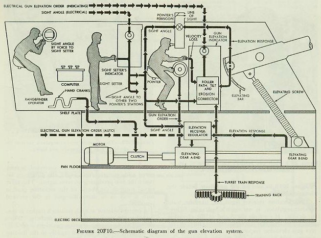
20F20. Operation of elevation equipment
Figure 20F10 shows a functional schematic of the operation of the elevation system. There are three duplicate sets of elevation equipment-one for each gun-only one of which is shown. The equipment is located on the shelf plate, at the pointers’ stations, and on the pan floor.
20F21. Local gun laying
In local gun laying, as explained in article 20F13, the computer furnishes the values of sight angle and sight deflection. Sight angle is received by phone from the computer operator and set into the sight setter’s indicator by the sight setter. Motion of the hand crank moves the line of sight in relation to the gun bore. Sighting through the telescopes, the pointers operate their handwheels to position the guns until the horizontal crosslines are on the target. The handwheels control either the A-ends of the elevating gears (hand drive), or the receiver-regulators (local power drive).
If manual drive is used, the operation is the same, except that manpower is supplied to the A-end from the hand cranks instead of electric power from the motor.
In primary, secondary, and auxiliary fire control, the guns are elevated in accordance with an electrical gun elevation order. In each case, the guns may be elevated in either indicator or automatic gun laying.
20F22. Indicator gun laying
In indicator gun laying the gun elevation order positions the following-the-pointer inner dials of the gun elevation indicators. The pointers operate their handwheels to match the dials. By so doing they control the A-ends of the elevating gears, which control the elevation of the guns. The elevation of each gun is transmitted mechanically from the elevating arc as elevation response back to the gun elevation indicator. Here the elevation corrections are added to gun elevation response to produce modified gun elevation, which restores the zero-reader dial and positions the follow-the-pointer ring dial.
In auxiliary fire control, sight angle is not available on the dial of the sight setter’s indicator, but must be supplied by the local computer or from some other source by telephone.
20F23. Automatic gun laying
In automatic gun laying the gun elevation order is received by the elevation receiver-regulators, which automatically control the A-ends of the elevating gears, and thus the elevation of the guns.
The receiver-regulators also receive sight angle and velocity loss for computing the erosion correction, and turret train response for computing the roller-path tilt correction, as do the elevation indicators.
20F24. Turret inputs and outputs
The quantities received by the turrets are:
1. Gun train order (automatic, indicating).
2. Gun elevation order (automatic and indicating).
3. Sight angle.
4. Sight deflection.
5. Adjacent turret train (in turrets 1 and 2).
The outputs are:
1. Turret train (information).
2. Optical range
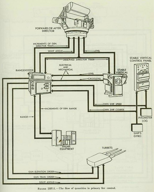
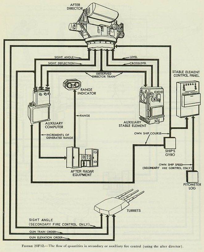
Some of the types of fire control which may be used were briefly discussed in article 20B4.
Figures 20F11, 20F12, and 20F13, which are flow diagrams for primary, secondary, and local fire control respectively, should assist in an understanding of what takes place in these types of control.
Back to top
