Part E: Main-Battery Plotting Room
20E1. Location
The main-battery plotting room is located opposite the secondary-battery plotting room. Its location below the waterline and beneath the armored deck is to ensure maximum protection from enemy action. The arrangement and location of the equipment differ somewhat among ships;
figure 20E1 shows a typical installation, while
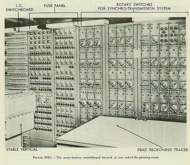
figure 20E2 shows the main-battery switchboard.
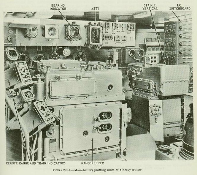
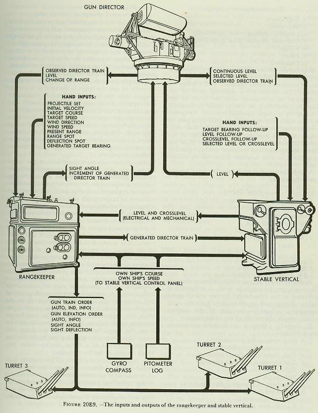
The principal items of equipment in the plotting room are: the Gun Director Mark 41 (stable vertical), with its control panel; the Rangekeeper Mark 8, the radar equipment associated with the forward director, and the main-battery fire control switchboard. In addition to these principal items, there are a gun train order relay transmitter, bearing indicators, range indicators, multiple turret train indicators, a graphic plotter on the range-keeper, director train indicators, telephone equipment, and various switches and signal lights. Some ships are provided with a dead-reckoning tracer in main-battery Plot.
The plotting room is the primary source of gun train and gun elevation orders. To it, in primary fire control, are brought the data measured and estimated at the directors; from it are transmitted the data used to position the gun.
20E2. Gun Director Mark 41 Mod 0 (stable vertical)
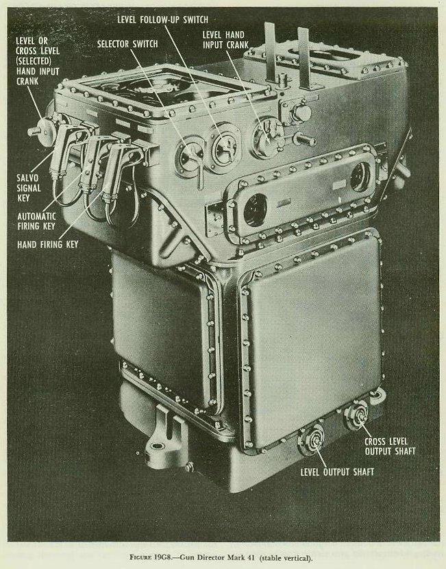
The general appearance of the stable vertical is as shown
in figure 19G8.
In the previous chapter the stable vertical was discussed only as an instrument which designates and maintains the true vertical and its associated horizontal plane, and by so doing, continuously measures level and crosslevel. Another function of the stable vertical is its use as a remote firing station. The utilization of it as such is associated with methods of aiming designated as continuous and intermittent. Intermittent aim is that method of aim in which target position is continuously measured in one coordinate and periodically measured in the other; thus it may be subdivided into selected elevation, in which bearing is the element continuously measured, and selected train, in which elevation is the quantity continuously measured.
If continuous aim is in use, it is possible to fire the guns at any point in the motion of the ship in roll and pitch. Thus this method may be called, as it is on the nameplates of the stable vertical, “continuous fire,” although this term must not be confused with the use of the same term to indicate a method of gun firing as defined in article 18A2.

Continuous aim is used under normal sea conditions. The stable-vertical selector switch is set to CONTINUOUS FIRE, and both level and crosslevel as generated in the stable vertical are transmitted continuously to the rangekeeper. This results in gun train order and gun elevation order being continuously corrected for inclination of the deck. The guns may be fired by closing a hand firing key at the front of the instrument. Note that the gun maintains its position in space, while E’g continuously changes as L’ changes.
Figure 20E3 illustrates continuous aim. (At times it is desirable to have the director pointer, rather than the stable-vertical operator, do the firing. This may be accomplished by keeping the stable-vertical key closed, so that the only break in the current, is at the firing pointer’s key. When his key is closed, the circuit is complete.)

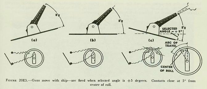
Intermittent aim is used when sea conditions make it difficult for the guns to stay on target. In this method of aim the guns are not continuously stabilized but move with the ship, as shown in
figures 20E4 and 20E5. It thus becomes necessary that the guns be fired only at such moments as aim is correct. To accomplish this, master-key fire from the stable vertical is used, preferably utilizing the automatic contact makers provided for this purpose.
The stable vertical is a device for indicating the true horizontal plane, and for measuring the values of level and crosslevel. It may be separately mounted or incorporated in a gun director.
Since at the stable vertical the quantities which are measured are level and crosslevel, the intermittent aiming methods must, from the point of view of the operator, be considered as selected level and selected crosslevel. Since selected crosslevel is less frequently used, only select level is described in detail.
In selected-level operation the selector switch is set to LEVEL FIRE, and a fixed value of level angle is set into the stable vertical by hand (or electrically from the director in some cases). This value is usually selected so as to cause aim to be accurate and thus the guns to fire at about the middle of the ship’s roll, and the same fixed value of selected level is transmitted from the stable vertical to the rangekeeper. It is apparent from
figure 20E4 that since the angle between the deck and the gun (E’g) remains constant, there is one and only one position of the deck at which the aim is correct; that is, when the value of L’, measured in the stable vertical, exactly equals the selected value of level (L’;) being transmitted. In order to ensure that the guns will fire at this instant, a set of firing contacts closes the circuit automatically when the above condition exists.
Any value of selected level L’j may be chosen.
Figure 20E4 shows the special case where L’j=0, and
figure 20E5 is an example where L’j=5 degrees.
Selected-crosslevel operation is similar to selected-level, except that transmission of level remains continuous while transmission of crosslevel is fixed.
20E3. Operation
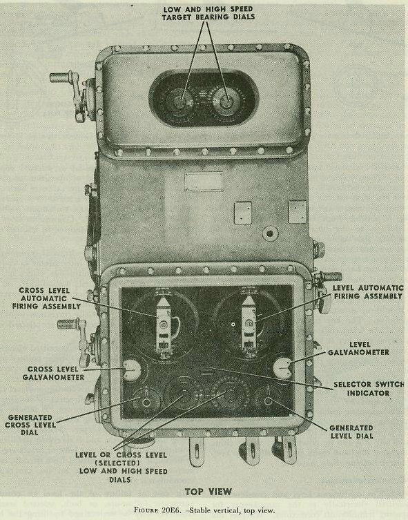
Figure 20E6 shows a top view of the stable-vertical face, with the various dials indicated.
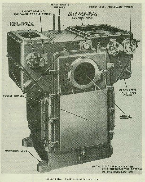
Figures 19G8 and 20E7 are side views, showing the arrangement of cranks, switches, and firing keys.
In the front right and left corners of the dial face are the generated level and crosslevel dials. These dials are driven by the L’ and Zh follow-up motors and continuously show values of L’ and Zh being generated.
In the center of the dial face is a small window indicating the setting of the stable-vertical selector switch, located on the right side of the instrument.
This window reads CONTINUOUS, LEVEL, or CROSS-LEVEL, depending upon the method of operation selected.
The selected level or crosslevel dials at the front center of the dial face are set by the hand crank on the front side of the instrument. This dial group shows the value of either L’j or Zhj, depending upon the method of operation selected. Selected values of level and crosslevel may be received by these dials electrically from the director, if the hand input crank is disengaged.
The level and crosslevel automatic firing contact assemblies referred to in article 20E2 are located at the rear of the dial face. These contacts are used only in intermittent methods of aim. When continuous aim is being used, the automatic contacts are by-passed.
When the guns are fired by selected level (or crosslevel) procedure, the automatic firing key located adjacent to the hand key must be closed when the battery is ready to fire. The actual firing instant will then occur when the automatic contacts are made. The inner contact remains in the position shown in the figure; the outer contact is positioned in accordance with the generated level (or crosslevel) angle plus the additional selected level (or crosslevel) angle, so that it oscillates back and forth with respect to the inner contact as the generated angle changes. The firing circuit is completed momentarily when the outer contact sweeps past the inner one, thus firing the battery automatically when the selected and generated values are equal.
The stable vertical contains a firing mechanism consisting of contacts and a firing delay compensator, so arranged that the firing time is advanced to compensate for the ejection time of the projectile, thus ensuring that it leaves the gun atthe selected value of level or crosslevel, as required.
These contacts may be connected, at the fire control switchboard, in series with the firing keys in the aloft director or at the stable vertical so that automatic selected level or crosslevel firing is possible from either of these stations. In addition to the above-mentioned automatic firing key, the stable vertical has a hand key which is normally used for continuous fire. In this type of fire, (luring which the guns are constantly stabilized, the hand firing key is part of the series firing circuit, and a selector switch shorts out the automatic firing contacts used in selected fire.
The hand firing key may also be used in selected fire, should the automatic firing mechanism become inoperative. The key is closed when the index marks of the firing contacts coincide.
A salvo-signal key is located at the front of the instrument and is used in conjunction with either firing key as a warning that a salvo is about to be fired.
At the rear top of the instrument can be seen the target bearing dial group. Normally, these dials are positioned by the B’r’ signal from director through automatic follow-up action. Under these conditions the target-bearing hand crank (fig. 20E7) is disengaged. If the automatic follow-up should fail, B’r' can be entered into the machine by engaging the hand crank and turning it to keep the target bearing dials matched.
20E4. Interrelationships
Selected or continuous level and crosslevel are transmitted electrically to the rangekeeper for computing trunnion-tilt corrections. Whether the transmissions are continuous or selected depends upon the aiming method of operation employed. In continuous aim, continuous values of both quantities are transmitted. In selected-level operation, a selected value of level and continuous values of crosslevel are transmitted. Continuous level and selected crosslevel are transmitted in selected cross-level.
Simultaneously with the electrical transmissions, and regardless of whether intermittent or continuous aim is employed, continuous values of both quantities are transmitted mechanically to the rangekeeper for computing deck-tilt correction (j’B’r’). Were these additional continuous transmissions not made, deck-tilt correction would not be practicable in selected level or selected cross-level.
Continuous level may be transmitted electrically to the aloft directors for follow-the-pointer operation by the director, thus permitting level operation in the director in the event the pointer’s telescope cannot be used. This continuous-level signal is also used in the aloft directors to stabilize the rangefinders and radar antennae. A selector drive is installed in the shafting which carries level and crosslevel to the rangekeeper. When a director is being used for search, and is receiving stabilization from the stable vertical, the selector drives are used to uncouple the stable vertical from the idle range-keeper. Thus undue wear on the rangekeeper mechanism is avoided.
In case of failure of the level or crosslevel automatic follow-ups, or both, selected level or crosslevel may be maintained by using the hand followups, the galvanometers, and the hand firing key.
Dials are provided to indicate values of target bearing, measured level and crosslevel, selected values of level or crosslevel, and firing-delay compensation.
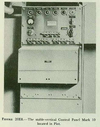
20E5. Stable-vertical control panel
This panel is shown in
figure 20E8. it contains the various switches, fuses, signal lights, and other apparatus necessary for the control of the stable vertical. The stable vertical panel also contains the switches operating the mercury cut-out valve which prevents malfunctioning of the gyro during high-rate maneuvers of own ship. These switches require synchro inputs of own-ship speed and course for their operation.
Inputs and outputs of the stable vertical and control panel are shown in
figure 20E9.
20E6. Rangekeeper Mark 8
The rangekeeper includes most of the controlling, computing, and transmitting fire control mechanisms for the battery. The instrument is a combined rangekeeper, bearing keeper, predictor, deck-tilt corrector, trunnion-tilt corrector, and graphic plotter. Given the hand and automatic inputs listed below, the instrument will compute, indicate, and transmit electrically the information necessary to point the guns and set the sights continuously, and to train the directors and radar antennas continuously on the target. Outputs include the necessary corrections for drift, for wind, for variation in initial velocity, for relative movement of ship and target, for tilt of the gun trunnions from a horizontal plane (trunnion tilt) and for inclination of the director roller path from a horizontal plane (deck tilt). A time-of-flight signal mechanism, which electrically actuates local and distant buzzers indicating the fall of salvos, is included. The graphic plotter automatically plots ranges, sight deflection and time, and the magnitude and time of application of range and deflection corrections. The rangekeeper is equipped with synchro transmitters and receivers, which are used for all electrical inputs and outputs, except for those received by signal lights and those transmitted to lights or buzzers.
1. Inputs. Inputs are introduced manually by knots, and automatically by mechanical and electrical transmission. Some inputs are used to set up the fire control problems, while others are concerned with the transmission of quantities and signals. Of these inputs, the following are used to set up the fire control problem:
Hand Inputs
a. Powder charge and projectile.
b. Initial velocity.
c. Target course.
d. Target speed.
e. Wind direction.
f. Wind speed.
g. Ship course.
h. Ship speed.
i. Present range.
j. Generated target bearing.
k. Observed director train.
l. Deflection correction (spot).
m. Range correction (spot).
n. Time.
o. Level.
p. Crosslevel.
Some of the hand inputs listed above are for emergency use when certain automatic inputs or motors in the instrument are inoperative. Items g, h, j, i, k, n, o, and p are set in by hand only when the corresponding electrical input fails. Items bb and cc below are used only when the electrical follow-up of sight deflection or sight angle, respectively, is inoperative. In the event of failure of the time motor, item ee below is used to drive the mechanism normally driven by that motor.
Mechanical Inputs
q. Level (continuous).
r. Crosslevel (continuous).
Continuous values of level and crosslevel, items q and r, are transmitted mechanically from the stable vertical to the rangekeeper, where they are used to drive mechanisms in the deck-tilt computer.
Electrical (Synchro) Inputs
s. Ship course.
t. Ship speed.
u. Observed director train (automatic).
v. Observed director train (indicating).
w. Range.
x. Level.
y. Crosslevel.
Ship course, observed director train (automatic), level, crosslevel, and range are each received by a pair of synchro receivers equipped with a follow-up device. The latter drives different parts of the mechanism in accordance with the value of the quantity controlling it. Ship speed is similarly received by a single synchro receiver. Observed director train (indicating) is received by a pair of synchro receivers which drive indicating dials only. These dials are used for the introduction of observed director train by hand. Similar dials are driven by the level and crosslevel synchro receivers, in addition to their function of controlling followups.
Additional inputs used only to transmit quantities or signals are:
Hand Inputs
aa. Selected train.
bb. Sight deflection.
cc. Sight angle.
dd. Range-scale shift.
ee. Manual power.
ff. Time of flight (setting of signal mechanism).
Electric (Other Than Synchro) Inputs
gg. Range-mark signal.
hh. Director-ready signal.
A director-ready signal, which indicates that the director is on the target in train, is received and indicated at the rangekeeper by two sets of signal lights. Range-mark signals received from the radar equipment actuate mechanisms in the graphic plotter which plot values of the radar range.
2. Outputs. Outputs transmitted electrically are as follows:
a. Gun train order (automatic).
b. Gun train order (indicating).
c. Gun elevation order (automatic).
d. Gun elevation order (indicating.
e. Sight deflection.
f. Sight angle.
g. Increment of generated director train.
h. Generated director train.
i. Time-of-flight signal.
j. Rangekeeper signal to rangefinders.
k. Plot-ready signal.
1. Generated change of present range.
Outputs a to h inclusive are transmitted by synchro transmitters. Outputs i and j operate buzzers at distant stations, while k controls signal lamps at distant stations. Increments of generated director train are transmitted to the aloft controlling director, where it enables the director to be trained automatically. As an auxiliary method of control, generated director train can be substituted in the rangekeeper and stable vertical for observed director train, in case the target is obscured or the transmission from the exposed director is temporarily interrupted. Gun train order (automatic) and gun elevation order (automatic) are transmitted to the turrets for automatic gun laying. Gun train order (indicating), gun elevation order (indicating), sight deflection, and sight angle are transmitted to the respective indicating instruments in the turrets and at other stations. There are no mechanical outputs.
One of the important functions of the rangekeeper is the generation and transmission of increments of generated director train. The quantity, as initially computed in the rangekeeper, is based on electrical inputs of own-ship speed and course, and estimates of target speed and course set in by the operator. Own-ship quantities are accurately measured, but the target estimates may be in error. As the director is trained automatically in response to the generated signal, the director trainer observes the target by means of his telescope or radar indicator. If it is seen that the director tends to drift off the target, the trainer, by means of his hand-wheels, adds the motion necessary to keep it on. Remote control of such corrections is also possible; the radar operator in Plot is provided with a separate train transmitter with which he can correct director train in accordance with his radar scope indications. A constant comparison of generated and observed director train is presented to the rangekeeper operator on dials in the rangekeeper. With this information available, the rangekeeper operator needs only to be assured that the director is on the target before adjusting the target estimates. The on target signal is given by the director trainer by means of a signal contact maker provided in one of his handwheels.
3. Generated director train. This quantity is an initial setting of director train plus the summation of increments of generated director train mentioned in the preceding paragraph. It is, therefore, the computed angle between the center line of own ship and the director line of sight measured in the plane of the deck.
Generated director train is transmitted to the train designator in the controlling director for follow-the-pointer operation by the director trainer, This use enables the director trainer to stay on the target in local power (or manual) operation, should the target become temporarily obscured. Lack of agreement between the generated and observed quantities is indicative of erroneous estimates of target movement used in the rangekeeper solution. It is emphasized that generated director train is not used to train the director in automatic operation.
4. Range. As originally designed, the range-keeper computes generated present range and advance range, which may be read on counters on the face of the instrument. Generated present range is the sum of initial measured range between own ship and target, computed change of range in a given time interval due to relative movements of own ship and target, and any range corrections that may have been applied. As previously stated, advance range, used for sight-angle computation, is the sum of generated present range, computed range predictions, and ballistic corrections. Both quantities (generated present range and advance range) are employed solely in the rangekeeper; they are not transmitted outside the instrument.
Generated change of present range is transmitted to the radar control console in the plotting room, and observed range is entered into the rangekeeper solution automatically. If the rangekeeper solution is incorrect, the radar operator at the control console may superimpose corrections on the transmitted signals, thus causing rotation of a solution-indicator dial on the rangekeeper. The rangekeeper operator then corrects the set-up by modifying the inputs of target course and speed, in order that the radar equipment may track the target correctly.
This method of ranging is known as aided ranging.
5. Corrections. The rangekeeper also computes trunnion-tilt and deck-tilt corrections, but does not transmit these quantities.
a. Trunnion-tilt correction. The computations made by the trunnion-tilt corrector are based upon measured values of leve1 and crosslevel received from the stable vertical and computed values of sight angle and sight deflection. The computed corrections are applied in the rangekeeper to sight angle and sight deflection before addition of these quantities to level and director train respectively, to form gun elevation and gun train orders.
b. Deck tilt correction. This quantity (jB’r’) is computed from observed director train received from the controlling director, and values of level and crosslevel received from the stable vertical. It is added to director train measured in the deck plane to obtain relative target bearing in the horizontal plane. This is needed, since the rangekeeper computes its solution in the horizontal. It can also be used to convert a value computed in the horizontal to one in the deck plane, as, for instance, increments of generated director train.
6. Graphic plotter. The graphic plotter is mounted on, and usually functions with, the range-keeper. As originally designed, it records observed ranges from several remote stations, direction and time of application of deflection and range spots, values of generated and advance range computed by the rangekeeper, and the value of advance range existing when the time-of-flight button is pushed; and it plots continuously a trace of sight deflection computed in the rangekeeper.
After completion of current alterations, the graphic Plotter will no longer receive and plot values of observed range from the several rangefinder stations, but instead will plot only values of observed range from the radar equipment. This will be entered into the rangekeeper solution automatically and plotted at the same time. Plotting of other quantities enumerated above will be carried out as heretofore.
Inputs and outputs. Inputs and outputs of the rangekeeper are shown in
figure 20E9 and
figure 20F11. 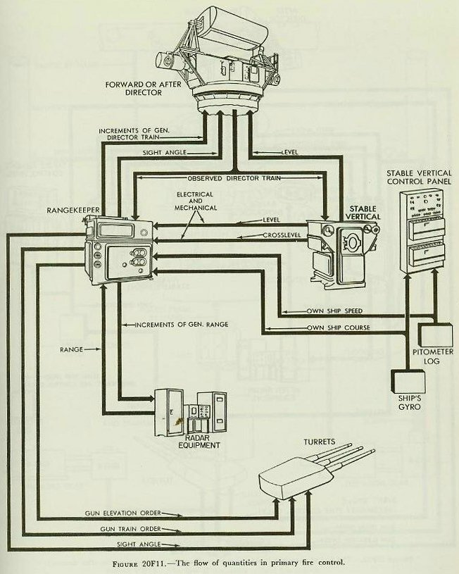
20E7. Analysis of rangekeeper set-up
Since the rangekeeper solution of the problem is based on inputs, of which A, target angle, and S, target speed, are estimated, it is obvious that the values of E’g and B’gr, as solved by the rangekeeper, will be correct only if the estimated inputs are correct.
The analyzing feature of the rangekeeper provides the means for correcting the errors in setting target course and target speed. This operation is known as rate control and is defined as “the solution for correct target course and speed by causing the generated range and bearing rates to agree with the observed values.” Note that only one combination of target course and speed will cause both range and bearing rates to agree, and that this combination is the solution.
The amount and direction of change of target speed and target angle to effect such agreement varies for different conditions of target motion.
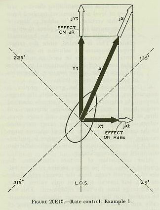
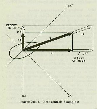
In the following discussion and in
figures 20E10 through 20E13, it will be noted that no consideration is given to own-ship motion. This is justified because the accurately measured quantities representing own-ship motion are automatically and continuously being introduced to the rangekeeper computing mechanism. It can be assumed then that errors in RdBs and dR are caused entirely by errors in the target motion quantities, and therefore exist only in the computed target motion rates, Xt anti Yt. In
figures 20E10-13, the initial motion of the target and the initial values of Xt and Yt are indicated by the solid arrows. The changes in the initial values are indicated by the outline arrows and the letter j.
Effect of changing S. The effect that changing S has on the relative motion rates depends upon the direction of target motion relative to the line of sight, or target angle, A. If target motion is toward the right of the line of sight, an increase in S will make the deflection rate algebraically more positive. If target motion is toward the left, an increase in S will make the deflection rate more negative. ‘When the estimated value of target angle indicates that the target’s motion is away from own ship, an increase in S will cause the range rate to become positive; and with the target motion toward own ship, increasing S will make the range rate more negative.
When the direction of target motion is along the line of sight (A = 0° or 180°), changing S affects dR a corresponding amount without affecting RdBs. When the direction of target motion is at right angles to the line of sight (A = 90° or 270°), changing S affects RdBs a corresponding amount without affecting dR.
With the direction of target motion other than directly along or at right angles to the line of sight, changing S affects both dR and RdBs. When the direction of target motion is closer to being along the line of sight than at right angles to it, as in
figure 20E10 (A between 135° and 225° or between 315° and 45°), changing S has a greater effect on dR than on RdBs. If the direction of target motion is closer to being at right angles to the line of sight than along the line of sight, as in
figure 20E11 (A between 45° and 135° or between 225° and 315°), changing S has a greater effect on RdBs than on dR.
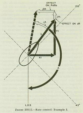
Effect of changing A. Changing A affects both dR and RdBs, the relative effect on each depending on the direction of target motion, or target angle, A. In the following examples, target speed, S, is assumed to be constant.
When the direction of target motion is closer to being along the line of sight than at right angles to it, as in
figure 20E12 (A between 135° and 225° or between 315° and 45°), changing A has a greater effect on RdBs than on dR. But, if the direction of target motion is closer to being at right angles to the line of sight than along the line of sight, as in
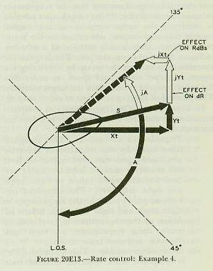
figure 20E13 (A between 45° and 135° or between 225° and 315°), changing A has a greater effect on dR than on RdBs.
From the diagrams shown in
figures 20E10 through 20E13, it is also apparent that when A is changed so as to bring the direction of target motion toward the direction of the line of sight, the deflection rate due to target motion diminishes, while the range rate due to target motion increases. It should also be noted that changing A from any value toward the 0° value causes dR to become more negative; while a change in A toward 180° causes dR to change toward more positive values.
When A is changed so as to bring the direction of target motion at right angles to the direction of the line of sight, the deflection and range rates due to target motion increase and diminish respectively. Furthermore, changing A in the direction of its 90° value causes RdBs to become more positive, while a change toward 270° makes it become more negative.
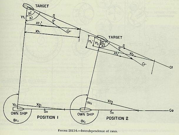
Suppose that a situation exists as shown in
figure 20E14. At position 1, own ship is on course Co at speed So, and its vector is correctly set in the range-keeper. The target is actually on course Ct at speed S, but because of an error in estimating the target motion, its vector is set in the instrument as though it were on course Ct' at speed S’. The respective target angles are A1 and A’1 and the range component of the vector S’ is equal to the range component of S. Under these conditions, dR computed by the rangekeeper agrees with the actual value of dR. It is apparent that there are many combinations of A’1, Ct’, and S’ which will have the same range component.
After an interval of time has elapsed, the two ships will have advanced, along their actual courses, distances proportional to their actual speeds, and will be at position 2. The actual target vector is still S: the target vector set in the instrument is still S’. The target angles between S and the LOS and S' and the LOS will have changed by the same amount that Br has changed, and the line components will be Yt2 and Yt’2. Evidently the computed value of dR will no longer agree with the actual value of dR; cR will be out of agreement with R, and it will be necessary to adjust the values of target angle and target speed set on the instrument.
At position 1, computed dR was correct. But computed RdBs was in error by the difference between Xt1 and Xt’1. The only set-up of the range-keeper which would produce the correct values of RdBs and dR at the same time is that in which A and S are used for the settings. Had both range and bearing rates been correctly set on the instrument at position 1, both of these rates would be correct at position 2, and cR would be in agreement with R. Thus, if the correct target track is to be established, the operator must adjust both rates.
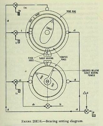
Since target bearing is generated in a manner similar to the generation of range, a disagreement between generated bearing (cBr) and Br will indicate that computed RdBs is wrong. (See
figure 20E16.) When RdBs is wrong and dR is correct, as at position 1 in the diagram, the operator can adjust A and S to correct RdBs without changing dR, by maintaining the dial reading of dR at the value indicated before the adjustment is made. Similarly, dR can be corrected without changing RdBs if conditions require such an adjustment.
The analytical aspect of rate control has been considered thus far. The following is a brief discussion of the manner in which rate control is actually accomplished by the rangekeeper operator.
Referring to
figure 20E16, the picture shown on the target and own-ship dials is merely an indication of the vectors for a typical example.
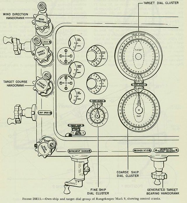
From the figure, it can be seen that the observed bearing as given by the pointer is farther to the right than the generated value which is read opposite the fixed index above own-ship dial. This indicates that the generated and observed bearing rates do not agree. If at the same time the generated range (see range-rate dial, fig. 20E15) is compared with the rate given by the graphic plotter, the whole picture becomes evident.
Let us assume that the generated range rate is increasing at 15 knots, while observed range rate is increasing at 10 knots. These facts indicate that the generated Xt component is too small and the Yt component is too large. If the operator changes target course to the right, the Xt component will be increased and the Yt component decreased, both of which are desired. If the operator increases target speed, Xt will be increased; but Yt, which is already too large, will be further increased. In the situation shown, target course is the dominant element and should be changed first. Before making a course change, however, the operator should ensure that present range (as shown in window at the lower left-hand corner of the rangekeeper face) is correct, if hand input is being used, and that the observed bearing pointer is reset opposite the fixed index.
In resetting bearing, reference to
figure 20E16 will show that all dials will turn together when jB is changed, and thus the present setting of target angle will be thrown off. For instance, after the observed-bearing pointer is reset on the fixed index, target angle will read roughly 180°, instead of 160° as it does in the figure. By use of the target-course crank it must be returned to its original value, 160°, and then the additional corrective change to the right, to about 140°, should be made. This change should bring the generated range rate closer to the observed graphic-plotter rate.
The operator observes the set-up as the range-keeper continues to generate the solution. He watches the bearing pointer to see if it continues to drift off in the same direction, stops on the fixed index, or reverses its motion. He continues to compare observed and generated range rates to determine if additional corrections are necessary. In all installations course and speed indicators are provided to assist the computer operator in visualizing the rate control situation.
Resetting the present-range dial to the correct observed value was required on earlier models of the rangekeeper, but recent models have a two-position shift lever on the present-range crank, with HAND and AUTOMATIC settings. When in AUTOMATIC, range from the rangefinders or radar is fed in automatically, so that the dial remains correct. Resetting is required only in HAND position.
The above example of rate control for the particular problem set-up shown is given to indicate the type of reasoning a rangekeeper operator must develop. It should be stressed that there is no hard and fast rule for the amount of change to make in Ct and S to obtain the proper solution. Long hours of practice in tracking actual targets alone will provide the experience required of an efficient rangekeeper operator.
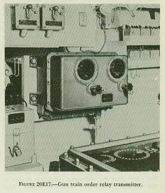
20E8. Gun train order relay transmitter
Additional equipment in the plotting room includes the gun train order relay transmitter shown in
figure 20E17, which relays gun train orders (for information) from the rangekeeper or aloft directors to the multiple turret train indicators. The relay transmitter prevents the heavy load on this circuit from adversely affecting the accuracy of transmission of gun train order to the guns. The instrument receives gun train order (indicating) from either the rangekeeper or the director (or in divided fire from both) and relays this order to the multiple turret train indicators. Normally this operation is automatic, but the instrument is provided with hand cranks and follow-the-pointer dials for emergency use. The relay transmitter can be used only when the main-battery switchboard is in operation.
In some installations the rangekeeper is equipped with a one-speed synchro transmitter for turret train information in addition to the usual two sets of synchro transmitters for gun train order (automatic) and gun train order (indicating). In such installations no separate gun train order relay transmitter is required nor provided.
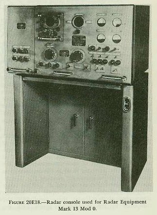
20E9. Radar equipment
The Mark 13 radar equipment is used to measure range in the main-battery fire control system. Range measurement is controlled by the radar range operator in the plotting room. From the Mark 13 radar console, range is transmitted to remote range and train indicators in the director, in the plotting room, and in topside control stations. The radar equipment may also be used for training the director in automatic control under conditions of poor visibility, since it has a narrow, well-defined beam and good accuracy in bearing discrimination.
See
figure 20E18.
20E10. Main-battery switchboard
The plotting-room fire control switchboard is shown in
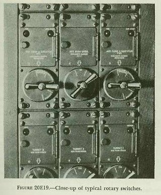
figure 20E2. The board consists of five panels of type-J rotary switches, a fuse panel, and a snap-switch panel for the interior communications circuits.
Figure 20E19 shows typical rotary-switch units.
The switchboard serves as a central point at which the synchro receivers and synchro transmitters in the various instruments and equipment comprising the fire control system can be energized and connected together as required for operation in different methods of fire control. Selections of signals to and from various elements of the system can be made, and substitute and alternate circuits can be set up in the event of casualties to some part of the system.
20E11. Miscellaneous equipment
Multiple turret train indicator. The plotting room contains one MTTI (see fig. 20E1), which shows the train of each of the three turrets and the difference between modified turret train response and gun train order. This instrument is the same as those used in the fire control stations.
Bearing indicator. This device (see fig. 20E1) indicates true target bearing, relative target bearing, and own-ship course. It is used for information purposes and is the same as those used in the fire control stations.
Dead-Reckoning Tracer Mark 6. This instrument, shown in
figure 20E2 is a plotting table with a pencil mechanism for charting own-ship course. North-south and east-west distance components, received from the analyzer of the dead-reckoning system, actuate the motors and mechanisms which drive the pencil carrier to record a graphic plot of the ship’s travel and also drive the dials which indicate the latitude and longitude. A clock mechanism is electrically connected to the pencil carrier to record elapsed time on the graphic plot. Any point defined by range and true bearing may be plotted relative to own ship on the plotting board. The equipment is used during shore bombardment operations.
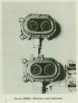
Director train indicators. Two director train indicators, shown in
figure 20E20, are mounted on the plotting-room bulkhead. These instruments show the train angle of the forward and after main and secondary battery directors.
Ready lights. The plotting room contains numerous salvo signal lights, turret ready lights, and other signals to provide visual information from other stations.
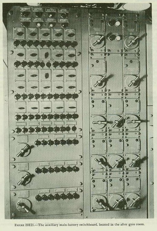
20E12. Auxiliary main-battery switchboard
In the event of casualties to the main-battery switchboard, gun orders can be routed from the directors to the turrets via the auxiliary switch-board. This board is located in the after gyro room and is connected with directors 1 and 2 and with turrets 1 to 3 by cables run in separate wire-ways widely separated from the primary cables. In order to shift control of the system to the auxiliary main-battery switchboard, switches located at the fire control stations and turrets are shifted from MAIN to AUX position.
The board consists of one switch panel and a snap switch and fuse panel. Indicator lights show the division of battery control between the directors. Type-j selector switches control the routing of gun orders and other data for the fire control installation.
Figure 20E21 shows the front of the switchboard.
Back to top
