| GENE SLOVER'S US NAVY PAGES NAVAL ORDNANCE AND GUNNERY VOLUME 1, NAVAL ORDNANCE CHAPTER 11 ROCKETS AND GUIDED MISSILES |
| HOME INDEX Chapter 11 Rockets and Guided Missiles A. Rockets and the rocket principle B. Rockets fired from surface craft C. Aircraft rockets D. Guided missiles |
 |
 |
| D. Guided Missiles 11D1. Definition of guided missiles The term “guided missile” has been defined by the Joint Committee on Guided Missiles as: “An unmanned vehicle moving above the earth’s surface, whose trajectory or flight path is capable of being altered by a mechanism within the vehicle.” This is a broad definition, but it limits the term to missiles in or above the atmosphere, and excludes such things as the guided torpedo. When we consider the guided missile as a weapon, we must qualify the above definition by adding that the missile must carry some lethal or useful military load. Guided missiles are designed for special purposes. The German V-2 rocket, for example, was designed for surface launching against surface targets. Several types of guided missiles are now under development. Among the missions assigned to such missiles are the following: Air-to-air (AAM). Air-to-surface (ASM). Air-to-underwater (AUM). Surface-to-air (SAM). Surface-to-surface (SSM). Surface-to-underwater (SUM). Underwater-to-air (UAM). Underwater-to-surface (USM). A number of special terms are encountered frequently in the study of guided missiles. Some of these terms and their meanings are as follows: Drone. A remotely controlled aircraft. Glide bomb. A winged missile powered by gravity. JATO. An auxiliary rocket device for applying thrust to some structure or apparatus. Mach number. Ratio of speed of an object to the speed of sound in air through which the object is moving. A missile climbing upward through the earth’s atmosphere at constant velocity has a constantly increasing Mach number, because sonic speed decreases with decrease in temperature. Sonic speed. The speed of sound. This is 766 mph under standard atmospheric conditions. It varies directly as the square root of the absolute temperature. Subsonic speed. Speed less than the speed of sound. Supersonic speed. Speed greater than the speed of sound. 11D2. History of guided missiles Guided missiles have come into being because of developments in several engineering fields. Part of this history begins with the development of air-duct engines within the present century. Guillaume of France outlined the principles of the modern turbojet engine in 1909, and the Italian Campini used the same sort of propulsion system in the first jet-propelled airplane, which he designed in 1932. In 1933 Leduc of France detailed the possibilities of the ram-jet engine, and in the same year Bleecker of the United States experimented with a pulse-jet engine. Meanwhile, the Wright brothers had begun the study of aerodynamic design at the turn of the century. Thereafter, a number of European scientists turned their attention to the various problems involved. In 1928 active study of flow phenomena got under way in the United States at the Langley Field Laboratory. At first thought, these early experiments may seem to have little relationship to modern guided missiles; but in fact all of them made some contribution, as did the various experiments with powder rockets reaching back to the 13th century. The Navy and the Army Air Corps initiated experiments concerned with flying bombs and aerial torpedoes in 1916. An aerial torpedo, launched from a catapult at the Naval Proving Ground in 1920, flew for about 15 minutes. Such early experimental models, however, were scarcely guided missiles, since they were not subject to control after launching. Then in 1924 a pilotless seaplane under radio control was launched successfully, although it crashed in landing. For a time thereafter, military experimentation in this area lagged, because of lack of funds and unsolved problems of devising suitable controls. But in 1926, Goddard of the United States perfected and tested the first successful liquid-fuel rocket. He also developed the first system of automatic rocket design by using vanes in the exhaust blast for steering. In addition, Goddard was the first to fire a rocket at supersonic speed. In 1936 the Navy initiated a project designed to produce a radio-controlled, pilotless aircraft which could be used as a target in gunnery training. Systems of radio control and stabilization were devised, and successful flight of a drone plane was effected in 1937. Shortly thereafter a drone plane was employed in gunnery exercise at sea. Radio control also came into use for purposes of testing new, experimental planes. Attention also was turned to the possibility of developing guided missiles in the form of aerial bombs or assault drones, and radio-controlled gliders. The latter were known as glombs, and were tested successfully in 1943, but their production was soon discontinued. However, several types of glide bombs were soon perfected, and used effectively in combat in World War II. The Navy also began experiments with a series of jet-propelled guided missiles in 1943; several types were brought into being but not employed tactically in World War II. Since the end of that war the Navy program of experimentation with guided missiles has been greatly expanded. |
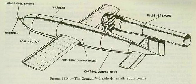
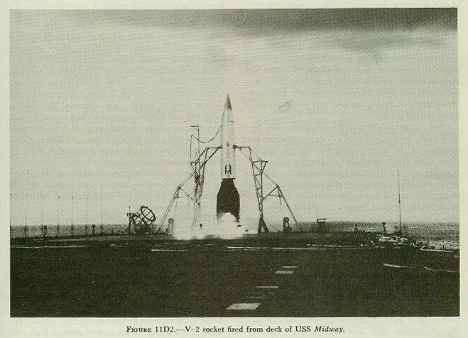
| 11D3. German long-range missiles During World War II the Germans achieved considerable success in the use of long-range missiles, including the V-I pulse-jet missile (buzz bomb) and the V-2 rocket. Both of these weapons served to effect area bombardment. About 15,000 buzz bombs and 2,600 V-2 rockets were launched against England and the channel ports. The external appearance of a buzz bomb is shown in figure 11D1. Overall length was a little over 25 feet, and weight at takeoff was 4,750 pounds. Speed attained in flight was about 360 mph, and maximum range was 150 miles. The V-2 (fig. 11D2) was radically different, being a true rocket of the liquid-fuel type. It had a takeoff weight of 30,000 pounds; which included 19,800 pounds of alcohol, liquid oxygen, and auxiliary fuels; a warhead of 2,200 pounds; and rocket structures weighing 8,000 pounds. Maximum velocity attained by this rocket was approximately 5,000 fps; exhaust velocity was 7,000 fps, and range was 200-300 miles. The V-2 rocket was stabilized by graphite vanes in the exhaust blast, and by the external fins. Earlier models were guided in flight by an auto-pilot set to maintain a predetermined course. 11D4. Mission of guided missiles All improvements in weapons, or attempted new weapons, are directed toward one or more of the following: 1. Increased striking range of the weapon itself, rather than increased range only of the ship or aircraft that launches the weapon. 2. Reduction in susceptibility to countermeasures. 3. Increased destructive effect gained by greater accuracy, greater explosive force, or both. Guided missiles are needed for both offensive an defensive reasons. A little imagination when studying the above list will lead to an understanding that if we can perfect missiles in these three ways, we will have powerful offensive weapons. On the other hand, we must assume that the enemy will also perfect guided missiles. To defend ourselves against these enemy weapons, we must have guided missiles capable of seeking out and destroying the enemy missiles in flight. It is essential that we gain and maintain supremacy in this new field. 11D5. The guided-missile principle We have seen that a guided missile is an unmanned vehicle whose trajectory is influenced by a self-contained mechanism. Quite a number of missiles now come within the scope of this definition. Unlike the Japanese “kamikaze” or suicide planes of World War II, such missiles are pilotless by definition. Each missile is used only once, however. This puts a premium on simplicity of design, low cost, and the possibility of quantity production. Until comparatively recent times, projectiles fired from guns were committed to a certain course and performance at the moment they left the gun muzzles. Then came the development of proximity fuzes, designed to produce detonation when certain conditions were met. The existence of such fuzes made possible one type of control, but a type which involves definite limitations at the longer ranges. A guided missile must have a mechanism that can make corrections in course during flight to compensate for initial errors in launching, deviation from course due to wind or other effects, and target motion. To be effective, then, a long-range guided missile clearly must have a propulsion system capable of producing high and sustained speed; must be able to traverse a considerable range; must incorporate a mechanism adequate for purposes of guidance; must have control surfaces capable of effecting necessary changes in flight path; and must carry a “pay load” appropriate to its mission. The development of such missiles has been associated with rocket development in general, with advances in jet propulsion and techniques of guidance or control, and with perfection of airframe design for supersonic speed. Guided missiles are still in their infancy, and it is entirely possible that they may constitute the standard bombardment weapons of the future. Great advances in their design undoubtedly will be made in the years ahead. Potentially, the guided missile is a weapon which may be used at long range, where conventional gunfire would be either impossible or ineffective. 11D6. Component parts In general, a guided missile is composed of four principal components: 1. Propulsion system. 2. War head and fuze. 3. Guidance system. 4. Air frame. In this volume, only the first two components will be considered. The various systems of missile guidance will be discussed in volume 3. 11D7. Propulsion systems Supersonic speed is the best defense of the guided missile against enemy countermeasures. Since a guided missile cannot easily detect or avoid countermeasures, it relies on its very high speed to reach its target. Similarly, when used defensively to intercept hostile aircraft or missiles, it must have a wide speed margin over its target. The German V—1 flew at 3,000 feet and 400 miles per hour; as a result, defenses were able to achieve as high as 95 percent effectiveness against it. On the other hand, no German V—2, a supersonic missile, was ever destroyed in flight by Allied countermeasures. Reaction-type power plants (rocket and jet engines) are the only presently known kind capable of propelling aerial missiles at these required supersonic and hypersonic speeds. We have already studied the rocket principle, which applies also to jet engines. Jet propulsion is defined as motion resulting from ejection of matter from within the propelled body to create momentum. To develop thrust, a means of ejecting matter must be found. This may be done in two ways. 1. Mechanical jets. Pumps or fans can be used to produce a jet of air, water, or other fluid. A rotating lawn sprinkler is mechanically jet propelled. 2. Thermal jets. A thermal reaction, usually oxidation, produces great volumes of gases at high temperatures and pressures, which expand through a ducted outlet, producing a jet. All practical jet engines work on the thermal principle. There are four varieties of reaction-type power plants: 1. Pulse jets. 2. Ram jets. 3. Turbo jets. 4. Rockets. Pulse jets. This engine, also known as an intermittent jet, includes an air scoop, a flapper valve system, a combustion chamber, and a discharge pipe. |
 |
 |
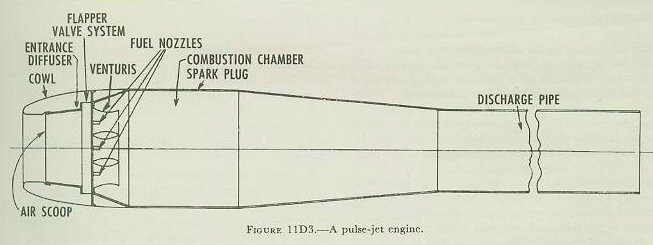
| The pulse jet is started by forcing compressed air through the spring-loaded flapper valves, adding the fuel (usually gasoline) under pressure, and igniting this mixture with a spark plug. See figure 11D3. The flapper valves prevent the expanding gases from escaping forward, but permit gases to rush out the discharge pipe at high velocity. This velocity is so high, in fact, that the gases overexpand and cause a partial vacuum in the combustion chamber. This action, plus the inrush of air caused by the motion of the motor through the atmosphere, opens the flapper valves and permits air to enter the combustion chamber. Part of the exhaust gases flow back up the discharge pipe and meet the air coming through the valves, compressing the new air slightly. This compression, plus residual burning fuel, plus the heat of the walls of the combustion chamber, ignites a new charge of fuel which enters at this time, and the cycle is repeated. It was this intermittent cycle, about 40-50 times per second, which gave the name of “Buzz Bomb” to the German V-1. The pulse jet is not used for manned flight. Advantages: 1. Light, economical, and easy to construct. 2. Uses atmospheric oxygen so needs no oxidizer. 3. Uses common fuels. Disadvantages: 1. Speed subsonic; limited to about 450 miles per hour. 2. Operation limited to earth’s atmosphere. 3. High fuel consumption. |
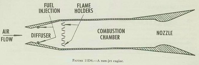
| Ram jets. This engine is also known as an “athodyd” (contraction of aero-thermodynamic duct) or a “flying stovepipe.” The latter designation is inspired by the shape of the engine and its lack of moving parts. The ram-jet engine consists of a diffuser or inlet air duct, a combustion chamber, and a discharge nozzle. Figure 11D4 is a sectional diagram of a ram-jet engine. Consider a piece of straight stovepipe at rest. If fuel were ignited in the middle of the pipe, the hot expanding gases would escape from both ends. Now consider the pipe moving along its axis at 400 miles per hour. Rammed air is traveling through the pipe at 400 miles per hour without combustion. When the heat of fuel combustion is added at a point near the forward end of the pipe, the gases seek to expand in all directions. Obviously, this expansion will be opposed by the “head” of air at the duct of the pipe. The only point of escape is at the rear. The pressure and heat produced by combustion are so great that the gas leaves the rear at 1,400 miles per hour. The mass of air entering at the front is thus rapidly accelerated to the rear, and produces thrust. In actual operation the ram jet has a divergent inlet nozzle. This raises the pressure of the air “head” by decreasing its velocity inside the pipe, and allows more heat to be added. The discharge nozzle is convergent, and thus increases the velocity of the jet stream. Entry head becomes still greater, and makes the acceleration greater; you can say of the ram jet that “the faster it goes, the faster it goes!” However, the ram jet must be boosted to a high speed before it will operate. This requires a booster that is larger and heavier than the ram jet itself. At low speeds-500 to 800 miles per hour-the ram jet uses fuel rapidly. As it reaches extremely high speeds at very high altitudes, however, the ram-jet unit itself gets hot from “skin friction.” This heat increases the pressure of the ejected gases, and relatively little fuel is required. There is a limit to this, however, for at extremely high speeds skin friction makes the metal of the ram jet white hot, and it soon collapses. Research will have to create metals to withstand this temperature if the advantages of the ram jet are to be fully used in guided missiles. In the near future, it may be possible to construct a ram jet limited in range only by the amount of fuel carried. Advantages: 1. Simple-no moving parts. 2. Light and cheap. 3. Easy to manufacture. 4. Uses common fuel. 5. Efficient at high speeds and altitudes. 6. Supersonic. Disadvantages: 1. Must be boosted to high speed before it will operate. 2. Limited to earth’s atmosphere. 3. Speed presently limited to about 2,700 miles per hour. |
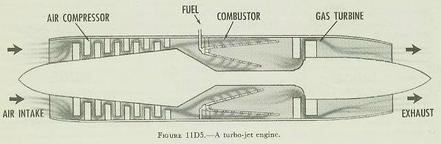 |
| Turbo jets. The turbo-jet engine includes an air scoop, a mechanical compressor driven by a turbine, a combustion chamber, and an exhaust nozzle. See figure 11D5. It does not require a booster. A turbojet engine provides good fuel economy at both high and low subsonic speeds. Turbo-jet propulsion has been used extensively in airplanes, since it is readily controllable in manned flight. It has also been used for the propulsion of long-range missiles. Velocities approximating Mach 1 are attained. One objection to the use of turbo-jet propulsion in expendable missiles, however, is that the mechanism is relatively complex and costly. In operation of the turbo-jet engine, the compressor, driven by the gas turbine, supplies air under high pressure to the combustion chamber, and the turbine absorbs only part of the jet energy. The result is an open-cycle gas turbine combined with a jet stream. The turbo jet is limited to less than the speed of sound. When it approaches the speed of sound, shock waves develop on the compressor blades and interfere with their operation. A recent development may permit turbo jets to operate up to Mach 1.2. But such jets would be relatively inflexible, and very inefficient at low speeds. Advantages: 1. Develops large static thrust. 2. Carries fuel only; gets oxygen from air. 3. Thrust practically independent of speed. 4. Burns common fuels. Disadvantages: 1. Subsonic speeds at present. 2. Complicated engine with moving parts. 3. Power limited by stresses on turbine blades. 4. Must operate in earth’s atmosphere. |
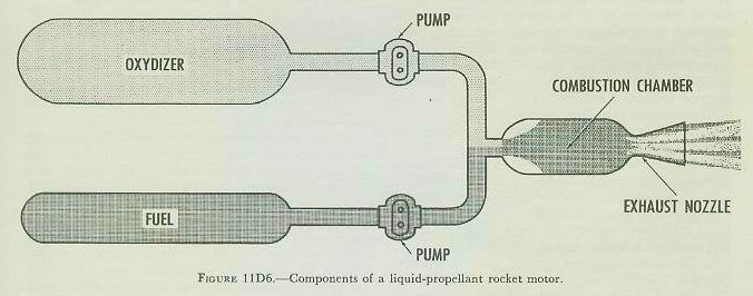 |
| Liquid-fuel rockets. To overcome the problems of weight and heat of burning for long-duration units, liquid-fuel rockets are used. The problems are alleviated by the fact that the combustion chamber may be made lighter and smaller than with a solid propellant. Fuel and oxidizer may be fed from their respective tanks to the motor by either the pressure feed system or the pump feed system. Figure 11D6 is a diagram of liquid-propellant rocket motor using the pump feed system. Most liquid-fuel motors are of the regenerative type. Those are built as a double shell, with separate openings for injection of fuel and oxidizer. Fuel enters the rear of the motor, flows between the walls, cools the inner surface, and makes possible the use of a thin-walled combustion chamber. The fuel then enters the forward end of the combustion chamber. This not only permits longer burning, but because of the preheated fuel it also increases the heat energy released on combustion. The fuel is ignited by a spark or a pyrotechnic device. Once initiated, combustion is self-sustaining, since fuel and oxidizer are continuously injected. The source of power for the pumps is a turbine driven by a steam generating plant. Since pressure is developed only on the output side of the pumps, the fuel and oxidizer tanks can be of relatively lightweight construction. The pressure feed system is similar to the pump feed system, except that pressure in the tanks takes the place of the pumps. The main disadvantage is that this pressure must be greater than the operating pressure of the combustion flask, which is 250-500 pounds per square inch. Consequently, the fuel, oxidizer, and pressure flasks must be of heavy construction. Advantages: 1. Relatively simple. 2. Practically unlimited speed. 3. Operates in any medium or a vacuum. 4. Relatively few moving parts. 5. Develops full thrust at takeoff. 6. Has less need for a booster than air-breathing engine. 7. Can utilize multiple-step rockets in combination with solid-fuel rockets. Disadvantages: 1. High rate of propellant consumption. 2. Short burning time. 3. Comparatively short range. 4. Cannot be stored fully fueled for long periods of time. 11D8. War heads and fuzes War heads. The payload of a guided missile is its war head. There is an optimum position of burst to accomplish the desired effect on the target. Within limits, the closer the burst to the target, the smaller the war head required. On the other hand there is a limit to the maximum size of war head for a specific missile. Any increase in the effectiveness of guided missiles will require either that we launch larger numbers of missiles against each target, or that we improve the guidance system. The latter is the most logical approach to the solution. Constant research is being devoted to improving methods of guidance. At present, there is no reason to believe that the war heads used by other military weapons cannot be adapted to guided missiles. The following types of war heads might be used: 1. Blast effect. Depends on shock wave generated by explosive force to do damage. 2. Fragmentation. Depends on explosive force to eject numerous metallic fragments at high velocities. 3. Shaped charge. Used for maximum penetration. 4. Explosive pellet. Contains numerous separately fuzed pellets that withstand initial ejecting force from war head, but detonate on impact with target. 5. Chemical. Contains gases or incendiary material. 6. Biological. Releases living micro-organisms to cause sickness or death. 7. Atomic. Depends primarily on blast and heat resulting from atomic fission or fusion. 8. Radiological. Depends primarily on saturation of target with radioactive material. The type of target is the most influential factor in the selection of war heads. It is emphasized that the war head, and the results it can achieve at the target, constitute the only justification for building and flying guided missiles. Fuzes. One or more fuzes may be used in conjunction with any of the above-listed war heads. Here again, the type of target is the most important consideration in the type of fuze desired. The fuzes used fall into three general categories: impact, proximity, and ground-controlled. 1. Impact. This fuze is actuated by inertia on impact, either at once or after a pre-set time delay. 2. Proximity. This fuze is actuated by some characteristic of the target, which causes the fuze to operate at a predetermined distance from the target. Following are five basic types of proximity fuzes: a. Radio-proximity (similar to VT fuzes). b. Pressure proximity. c. Electrostatic proximity. d. Photoelectric proximity. e. Acoustic proximity. 3. Ground-controlled fuzes. This fuze does not contain the mechanism for determining the proximity of the target. When the missile gets close enough to its target, a signal to detonate the missile is sent from a station on the ground. A fuze may appear to be a minor component of a guided missile, but a poorly designed or wrong-type fuze can render an otherwise powerful weapon useless. 11D9. Problems of guided-missiles design A guided missile must withstand very heavy acceleration forces and inertia loads produced by rapid turns at high speed. Materials used in construction must also withstand very high temperatures produced by air resistance (external), and fuel combustion (internal). It is axiomatic that if the missile becomes misshapen, it will fall out of control. From the aerodynamic standpoint, a long-range guided missile must have an airframe adaptable to very high speed and precise control. The missile must travel at supersonic speed to realize the full potentialities of jet propulsion and achieve greatest benefit of surprise at the target. One of the challenging needs is to reduce drag: resistance to motion through the air. Drag increases rapidly as missile velocity increases within the sonic range: within this range it is difficult to effect controlled flight as acceleration increases. The Germans met the problem in their V-2 rocket by installing graphite control vanes within the jet stream; these vanes effected control within the sonic range and were burned out when the V-2 attained supersonic speed. Thereafter, the surfaces in the air stream provided control. The range attained by a long-range missile depends primarily upon maximum velocity of that missile. Maximum velocity, in turn, is conditioned by the amount of fuel, the exhaust velocity when the fuel is being burned, and the effect of drag upon rocket velocity. For example, one variable is the mass-ratio of the missile, which represents comparison of (1) takeoff weight with fuel load, and (2) weight without fuel load. The theoretical mass-ratio of the V-2 rocket was about 3: 1; however, its actual performance was more nearly represented by a mass-ratio of 2.2: 1. In preceding discussions we have noted that many short-range rockets depend upon solid fuels for propulsion. The burning rate of solid fuels can be inhibited or delayed, but even so, solid-fuel rockets are not preferred as long-range vehicles. This is because their combustion chambers must be as large as the fuel charge, and must have relatively heavy walls to withstand the forces of combustion. In other types of long-range missiles it is possible to have small combustion chambers, into which fuels are drawn as needed from fuel tanks of much lighter construction. Thus kerosene or gasoline carried in tanks has commonly been used as fuel for air-duct engines. In liquid-fuel rockets, however, where fuel consumption is relatively high, the development of superior fuels becomes a critical consideration. The Germans used liquid oxygen and alcohol in the V-2 rocket. They also developed a nitric acid and hydrocarbon combination, and a hydrogen peroxide and hydrazine mixture for use in rocket propulsion. |
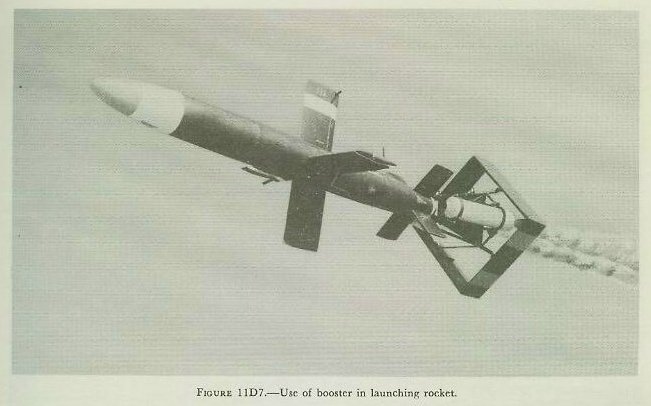 |
| 11D10. Single-step versus multiple-step rockets A rocket missile which has a single propulsion unit containing a charge which burns continually to the point of exhaustion is a single-step rocket. Such a rocket has the inherent disadvantage that the weight of all structures (less weight of consumed fuel) must be retained throughout the period of acceleration. A multiple-step rocket, on the other hand, incorporates one or more propulsion units which are discarded as rapidly as they serve their purpose. Step 1 is fired initially and burns to exhaustion. Step 2 now carries on the work of acceleration until it, too, is exhausted, whereupon step 3 is ignited and step 2 is discarded. This process continues until all steps incorporated in the rocket are consumed. Figure 11D7 shows a simple two-step rocket, in which a booster is used to give the missile its initial acceleration. When the booster is exhausted the propellant of the larger rocket will be ignited, and the booster will fall away. The potential superiority of a multiple-step rocket, from the standpoint of achieving high velocity, will now be apparent. This superiority stems from the fact that it is not necessary to accelerate the entire initial mass (less burned propellant) except during the burning of the first stage. It will also be seen that the proposed German A-9 and A-1 combination, previously mentioned, represented a sort of multiple-stage rocket. The A-10 rocket incorporated the first stage and the A-9 rocket incorporated the second stage. 11D11. Launching problems The Navy problem with respect to the launching of long-range missiles is complicated by the fact that launchers must be compact for shipboard installation, and that decks of ships do not provide the relatively stable base for launching that is provided by a land area. Launchers may be either fixed, in which case the missile is dispatched in the fixed direction and subsequent control must be provided to guide the missile to the target, or trainable, so that the missile is initially dispatched in the direction of the target. A fixed launcher is comparatively simple, but necessitates employment of rather exacting guidance during flight for each missile, and can be effective only against long-range targets. A trainable launcher makes less demand upon guidance in flight at short range, but is a much more complex structure from an engineering standpoint. Among the first guided-missile launchers to be used were gravity launchers for the release of short-range glide bombs. Essentially, such launchers are modified bomb racks. The launching thrust is provided by gravity, and initial train is effected by maneuvering the airplane. Early types of glide bombs such as the Bat were launched in this manner. Pit launchers were constructed to fire V-2 rockets. Within the pit the missile rested on its stabilizing fins in a vertical position; the rocket provided its own launching thrust. Such a pit launcher is an example of a fixed launcher. |
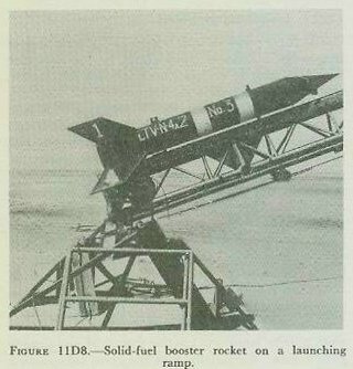 |
| Various types of inclined-ramp launchers, such as the one shown in figure 11D8, have been tested in experimental work. Such a launcher must provide for whatever control and initial propulsion are necessary to get the long-range missile on the way to the target, so that the missile’s own propulsion and guidance systems may function effectively. Essential components may include a set of rails along which the missile slides in the launching process. Such a launcher must also provide stable and rigid support, meet general requirements of compactness, and withstand the blast of the missile or its auxiliary boosters. Some long-range missiles, of course, have propulsion systems which do not function until the missiles have been accelerated to a requisite velocity. Booster units can be employed singly or in combination to supply the thrust necessary to produce this velocity. The thrust can also be provided by action of a catapult, which also gives support and direction during the launching period. The Germans used a catapult system to give initial acceleration to their V-1 bomb. A catapult is likely to be large, complex, and heavy; on the other hand, it may be used over and over again. It is possible, moreover, to use a catapult and booster charges in combination. Special gun types of missile launchers have also been developed. |
| 11D12. Missiles in use in the Fleet Although it is not possible in this volume of this course to go into detail regarding guided missiles that are now operational in the Fleet or under development, chiefly because of security classification, it is possible to survey very briefly here a few important types of missiles concerning which unclassified information is available. Missile types while under development are identified by code names rather than by descriptive nouns followed by mark and mod numbers. The best known United States Navy missile at the present time is a surface-to-air (SAM) type known as the Terrier. Terrier is the chief armament of GAG ships. At least one DD is being modified to carry it, and it will also be mounted on some new frigates. It is a 9-foot-long rocket-propelled weapon, which starts its flight from a twin launcher on the ship’s deck. The booster which gives the missile its start is nearly as long as the missile. The booster drops off after it burns out. The missile is guided electronically by the launching vessel. |
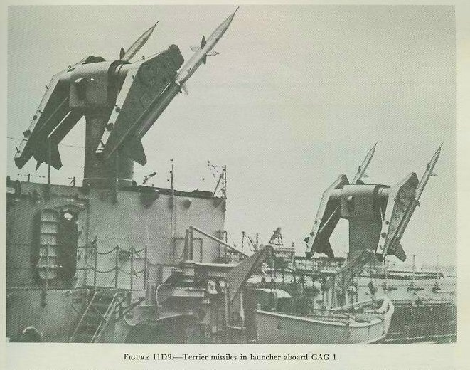 |
| The twin launchers on CAG vessels (the present two are former CA’s) are mounted above ammunition hoists which mechanically lift the missiles into the launcher. Reloading can be done twice a minute. It has been stated that two Terriers are normally sufficient to bring down any aircraft. Figure 11D9 shows Terriers in their launchers aboard GAG 1. An Army-developed missile similar in mission to Terrier is Nike, which is used in defense of ground installations and cities. Nike is not fired from naval vessels. Talos is a newer naval SAM larger than Terrier. At least one light cruiser is being modified to carry it. Regulus is one of several SSM’s developed for naval use. It is a high-subsonic-speed pilotless bomber which can be launched from any of several types of ship, including submarines. It can be fired from demountable launchers or from steam catapults. Another SSM still under development is the Loon. |
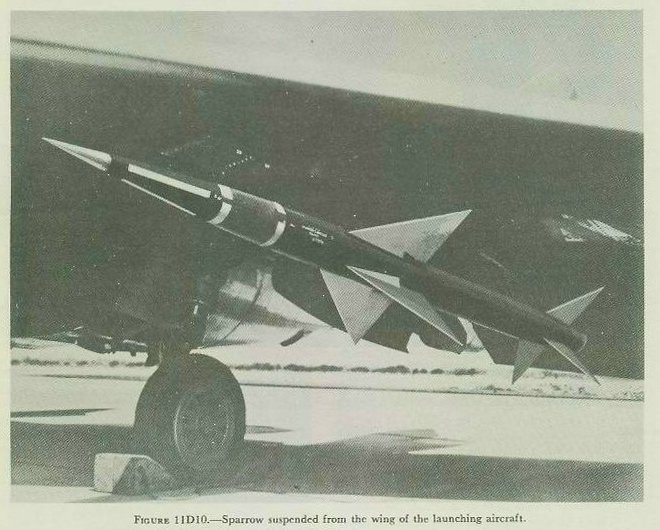 |
| Sparrow is a rocket-propelled AAM now operational in the Fleet. (See fig. 11D10.) It is guided by a radar beam transmitted from the launching aircraft. Sparrow is about 12 feet long, weighs around 300 pounds, and can attain a speed of 1,500 knots within a few seconds after launching. It has proved effective against both high-and low altitude targets, even while they are taking evasive action. Sidewinder is another rocket-propelled AAM. At this writing, details of this missile are classified. Development is close to completion on the AUM Petrel. This is essentially a homing torpedo mounted in an airframe with its own jet engine. It flies for some distance after launching, jettisons its airframe and engine when it strikes the water, and then functions as a homing torpedo against a submerged or partly submerged target. Aerobee is a research vehicle. It is a rocket capable of speeds up to 2,000 knots and altitudes of 78 miles. It carries instruments rather than a war head. |