| GENE SLOVER'S US NAVY PAGES NAVAL ORDNANCE AND GUNNERY VOLUME 1, NAVAL ORDNANCE CHAPTER 11 ROCKETS AND GUIDED MISSILES |
| HOME INDEX Chapter 11 Rockets and Guided Missiles A. Rockets and the rocket principle B. Rockets fired from surface craft C. Aircraft rockets D. Guided missiles |
| A. Rockets and the Rocket Principle 11A1. Definitions A rocket is a missile propelled by the escape of gases produced from the burning of solid, liquid, or gaseous propellants completely contained within itself. A true rocket by definition does not, for example, use atmospheric oxygen to burn its fuel. |
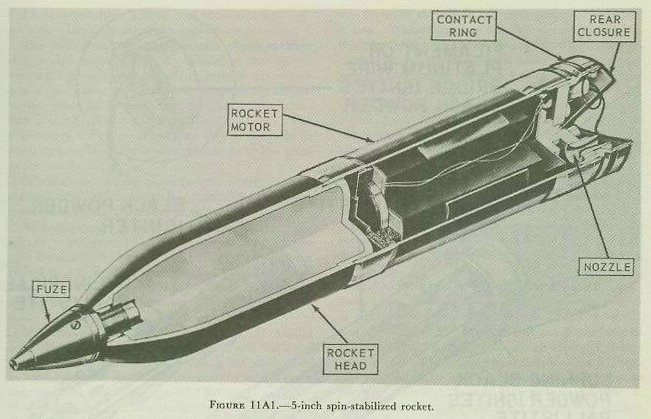 |
| Figure 11Al shows the external appearance of one type of rocket. The head of this rocket contains a high-explosive charge and a nose fuze to initiate detonation. The motor contains the combustion chamber, and houses the propellant charge. Hot gases from the combustion chamber issue from a nozzle at the after end of the assembly. Rockets exhibit two characteristics unique in the field of propulsion: (1) the propulsive force delivered is independent of atmospheric air, and thus the rocket may be propelled through empty space, and (2) the propulsive force is unaffected by the velocity. One of the challenging problems in rocket design is to develop an acceptable degree of stabilization in flight. The rocket shown in figure 11A1 represents a spinstabilized rocket. 11A2. History of rockets Rockets were used in the Far East as early as the 13th century. In the first decades of the 19th century several western armies employed rocket projectiles with greater or lesser success, a notable incident in the history of our own country being the use of rockets by the British during the attack on Washington in the War of 1812. But the military use of rockets languished after the middle of the 19th century, attention being diverted from them by improvement in guns and gunnery. Projectiles fired from guns proved to be superior to rockets in both range and accuracy. So for many years the employment of rockets was largely associated with pyrotechnic displays. During World War II, however, the development of military rockets under-went a considerable revival in the United States, Great Britain, Germany, and the U.S.S.R. Short-range rockets were developed for use against shore installations, ships, tanks, airplanes, and personnel. The Germans produced a long-range rocket missile known as the V-2. 11A3. Principles of rockets A rocket motor is a metal tube that serves as a combustion chamber. The burning propellant generates hot gas, and the gas pressure within the combustion chamber rises quickly to some value determined by the amount and characteristics of the propellant and the size of the nozzle or nozzles. The gas exerts approximately the same outward pressure on each square inch of surface within the combustion chamber; however, the gas rushes out of the nozzle without exerting any force upon the area of the opening, but with exertion of full force upon the corresponding area at the forward end of the combustion chamber. Thus a net force or thrust acts in the forward direction. The magnitude of this force is roughly the area of the orifice in square inches multiplied by the internal pressure in pounds per square inch. Fundamental to rocket propulsion, then, is the conversion of heat energy into kinetic energy by an adiabatic expansion. This poses two basic problems: (1) to generate gas under high pressure and at a constant rate-a problem of chemical reaction; and (2) to direct the high-pressure gases into a high-velocity stream-a problem of nozzle design. Pressure in a rocket motor depends largely upon the burning rate and escape rate. In the case of solid-fuel rockets, for example, the composition of powder, shape of grain, and rate of burning, which have important relationships to performance as discussed in chapters 2 and chapters 3, are also important factors in rocket design. a. Rocket motors. The thrust of a rocket motor is an equal and opposite reaction to the expansion of gases discharged at the nozzle; and since the expansion of these gases is maximum in a vacuum, rockets function most efficiently in such a medium. Rocket motors contain all the essentials for functioning, and do not require atmospheric oxygen for combustion. |
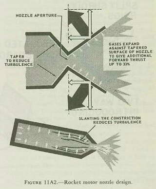 |
| Consider the nozzle in a little more detail. The function of the nozzle is to permit the hot gas produced by the burning ballistite propellant to flow out of the rocket motor, pushing the rocket along as it goes. The shape of the nozzle determines the characteristics of gas flow, and hence has much to do with how efficiently the gas flow propels the rocket. Gas flow must be smooth (nonturbulent). For a smooth, controlled trajectory, it must produce thrust along the long axis of the rocket. And the nozzle must be designed to develop every possible bit of thrust from the flow. By tapering the rear of the chamber so that it narrows smoothly toward the nozzle aperture, a smooth, nonturbulent flow of escaping gas is created. This tapered section forms the forward half of the nozzle. The tapered extension, forming the after end of the nozzle, which leads outward from the nozzle aperture, forces the escaping gas, as it expands to furnish additional (about 33 percent) forward thrust. (Fig. 11A2.) Many rockets have a number of nozzles, rather than just one. The same principles apply there. The rocket MOTOR TUBE contains the propellant charge and igniter. It is a combustion chamber in which the propellant is burned to provide the motive power (hot gases) for the rocket. It generally threads to the rocket or an adapter in the base of the head, and is usually shipped separate from the head. The diameter of the motor is less than that of the head in some rockets; in others its diameter is about the same as the head�s. |
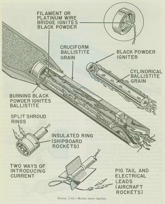 |
| The IGNITER contains black powder loosely packed, and an electric SQUIB with a low-resistance bridge wire running through a match composition. All present types of rocket motors are initiated electrically. As figure 11A3 shows, the firing impulses may be transmitted either (in aircraft rockets) by a pigtail lead from the rocket plugged into a source of firing current, or (in surface-launched rockets) by contact surface on the shroud surrounding the rocket�s tail. |
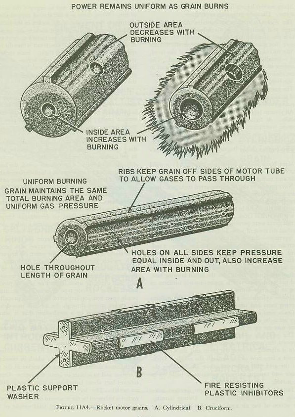 |
| Most Navy rockets use either (fig. 11A4) a solid cruciform grain or a cylindrical grain with an axial hole and radial perforations. The latter, often used in Navy ground or shipboard mounted rockets, is characterized by three ridges spaced 120 degrees apart and running longitudinally along the grain. The cruciform grain, usually found in Navy aircraft rockets, in section is a symmetrical cross. If all of the exterior surface of this grain were permitted to burn, there would be a gradual decrease of area, and the burning rate would be regressive----that is, the rate of gas production would decrease as the grain continued to burn. Since a uniform burning rate is desired, a number of slower burning plastic strips or INHIBITORS are bonded to certain parts of the area exposed on the outer curved ends of the arms. These slow the initial burning rate, and gas production rate is approximately uniform as long as the grain burns. Hollow cylindrical grains have inherently uniform burning rates and usually require no inhibitors. Grain sizes vary according to the motor in which they are to be used. Most use only a single grain, but some may use up to four. The grid is a metal piece near the nozzle which supports the propellent grain so that sufficient clearance is allowed between the grain and the nozzle to permit a free flow of gas through the nozzle. Without the grid, the grain will move aft, blocking the nozzle and causing excessive pressures to build up in the motor. Tail fins provide stability in flight, prevent tumbling, and ensure head-on impact. During burning, the action of the air against the fins tends to resist side forces of the nozzle and to improve the accuracy of fire. When there is a tail shroud around the fins, it supports the rear end of the rocket in the launcher. Most newer shipboard-fired rockets are SPIN-STABILIZED; that is, their nozzles are canted to exert torque as well as forward thrust. The result is that the rocket spins like a gun projectile in flight. Such rockets, of course, have no fins. Since spin begins as soon as the propellant starts to burn, the stabilizing effect begins as soon as sufficient thrust is developed to launch the rocket. Aircraft rockets are fin-stabilized designs. (To save space, folding fins that open on launching are often used.) Fin stabilization is poor when a rocket is launched at zero or low air speed (as is the case on surface craft); in aircraft, however, the plane�s air speed ensures good stabilization at the instant of launching. Rockets have been designed with canted fins, to produce spin. This kind of design is, however, subject to the drawbacks common to other finned rockets. b. Rocket heads. As previously noted, the head of a conventional rocket contains a high-explosive charge capable of being detonated by action of a fuze or fuzes. Use of centrifugal force and setback to arm fuzes, as in gun projectiles, is not universally applicable to rocket fuzes. In part, this is because rockets accelerate at a lower rate than do gun projectiles; moreover, with fin-stabilized rockets no centrifugal forces are available. For these reasons various other devices are employed to arm rocket fuzes. The fuzes of some antisubmarine rockets, for example, are armed either by hydrostatic pressure or by rotation of a propeller after travel of 15 to 20 feet in the water. When armed, such rockets detonate upon impact with any solid object. Several methods have been utilized to arm the fuzes of barrage or bombardment rockets so that they will detonate upon impact or after a predetermined delay. In one type of nose fuze, arming depends upon rotation imparted to a small propeller as the rocket moves through the air. A base-detonating type is armed by a mechanism that is actuated by pressure in the rocket motor during burning. On the other hand, fuzes used on spin-stabilized rockets may be similar to the fuzes of gun projectiles, since centrifugal force is present. c. Rocket launchers. Modern rockets are launched from various types of launchers, which in essence are mechanisms designed to point the rocket in the right direction and to actuate or ignite the motor. One significant fact about launching is that there is little or no recoil. The forward momentum given to the rocket is balanced by the rearward escape of propellant gases. Therefore, a very large total weight of �pay load� may be fired from boats, airplanes, or other conveyances which could not possibly withstand the recoil shock incident to firing equivalent projectiles from traditional types of larger guns. This is why the development of aircraft rockets, to cite one example, has been so significant. Inability of aircraft structure to stand up under the recoil shock of conventional-type guns had long been a limiting factor in aircraft armament. Until the rebirth of military rockets occurred, the largest projectile fired by most aircraft guns weighed only 2 or 3 pounds. The modern rocket-firing plane, however, is capable of launching rockets which weigh over 1,000 pounds. It also is noteworthy that many rocket launchers are relatively light in weight, simple, inexpensive, and more readily replaceable than comparable guns. On the other hand, much more propellant is required to bring a rocket up to a given velocity than is the case with a gun projectile. Moreover, rocket fire (with conventional short-range rockets) launched from the ground or from the deck of a ship compares unfavorably in accuracy with gunfire. Shipboard rocket launching devices always have a tube or rail which supports the rocket until firing, and guides it during the critical initial portion of its trajectory. This is necessary because, especially with fin-stabilized rockets, the stability of the rocket is relatively poor until it attains a fairly high air speed. On fixed-wing aircraft, as has already been explained, fin stabilization of rockets is effective at the instant of launching because of the plane�s air speed. Rocket launchers in aircraft are therefore merely supports which hold the rocket until launching, and then release it as the propellant is ignited. These are called �zero length� launchers. Shipboard launchers may be of �repeater� design to fire rockets successively at short intervals from a magazine or loading device. Electrical contact to the rocket�s squib in such launchers is made through a set of contactors which rub against insulated metal contacts on the rocket. In aircraft launchers, only one rocket is fired per launcher per flight. The electrical connection from plane firing system to rocket is made through pigtail leads and plugs, which part upon firing. 11A4. Rocket trajectory and stabilization Mention has been made of the fact that conventional rockets are less accurate than gun projectiles. One reason for this is that gun projectiles are guided by the gun bore during the entire period in which the propellant is burning and maximum velocity is being attained. A rocket, on the other hand, is guided by its launcher, if at all, during only a very small portion of the time that its propellant burns; in all cases, maximum velocity of the rocket is attained after it has left the launcher, and in some cases after the rocket has passed through hundreds of feet of free flight. In addition, the center of gravity of a gun projectile remains fixed in position in relation to the projectile while the latter is in flight, whereas the center of gravity of the rocket necessarily shifts in relation to the rocket as the fuel in the motor is consumed. After a rocket has attained maximum velocity, it may traverse a trajectory similar to the path traversed by a gun projectile. On the other hand, it is possible to place lifting surfaces (wings) on the rocket head, which will cause the missile to follow a glide path rather than a purely ballistic path, once acceleration is completed. The older type of rockets which came into widespread use during World War II were fin stabilized. Such rockets have the advantage of being relatively simple to manufacture, but are likely to prove somewhat cumbersome in handling, launching, and stowing. It may be pointed out, however, that fin stabilization is the type associated with a glide path of flight, and that stabilizing fins, with proper adaptation, may be used as rudders and elevators in controlling the path of flight. These facts take on special significance when we consider the potentialities of guided missile. Spin stabilization has also been used extensively in the case of rockets. A spin-stabilized rocket, like a gun projectile, tends to maintain a relatively stable course because of the gyroscopic effect resulting from its rotating motion, which in part counteracts forces that otherwise would produce deviation in line of flight. As a case in point, one type of 5.0-inch spin-stabilized rocket developed during World War II had a nearly flat trajectory at short ranges, and rotated at about the same or even higher speed than 5�/38 caliber projectile. In a gun projectile, rotary motion or �spin� is imparted by rifling of the gun barrel. Spin-stabilized rockets, however, achieve a spinning motion because they have several nozzles, slightly canted in position. Since fins are absent, such rockets can be relatively compact, which makes for greater convenience in handling, launching, and stowing. The degree of stabilization may also be considerably greater than that of fin-stabilized rockets. The old fin-stabilized 4.5-inch barrage rockets, for example, had a dispersion of from 20 to 40 mils, whereas the comparable figure for spin-stabilized rockets is about 20 mils. When fired forward from airplanes, fin-stabilized rockets achieve a much better performance. Fired from aircraft, dispersion of fin-stabilized rockets may be no more than 6 to 8 mils. Comparable dispersion of gun projectiles would be a single mil or less. |
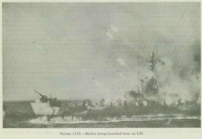 |
| It therefore is evident that the accuracy of conventional-type rocket fire is not on a par with the accuracy of gunfire. Rockets, however, have proved to be extremely valuable weapons for special purposes. Examples include the employment of rockets in antisubmarine attacks, and the saturation of enemy-held beach positions by rocket fire launched both from airplanes and from the decks of landing ships. Figure 11A5 shows barrage rockets being launched from an LSI which is moving in toward a beach. 11A5. Rocket fuels From the standpoint of fuels there are two general types of rockets: those incorporating liquid-fuel units as typified by the German V-2, and those incorporating solid-fuel units as represented by various barrage rockets. In liquid-fuel rockets, the fuel and the oxidizer are carried in separate containers from which they are ejected into a relatively small combustion chamber where the propelling reaction takes place. A comparatively elaborate mechanism was used in the V-2 rocket to control this use of fuel and oxidizer; however, simple designs have been developed subsequently which permit the use of liquid propellants in high-performance antiaircraft rockets, less than 4-inch diameter, capable of developing high thrust for a short period of time. Also the fuel tanks of liquid-fuel rockets for guided missile propulsion can be so located that change in center of gravity is reduced to a minimum as fuel consumption proceeds. Among the advantages of solid-fuel rockets is simplicity of design and operation. A single chamber serves as a container for the propellant and as a combustion chamber. Rate of gas production is controlled by the chemical composition of the propellant (especially by the ratio of the oxidizing agent to the fuel), by the operating pressure and temperature, and by the shape of the propellent charge and combustion chamber. In some cases inhibitors, consisting of slow-burning material attached to certain surfaces of the powder grain to delay combustion, are used. A disadvantage of solid-fuel rockets is the relatively great weight of the motor housing. 11A6. Naval uses of solid-fuel rockets Rockets (but not guided missiles) fired by naval ships and aircraft are designated by head diameter in inches. (This is analogous to the caliber of gun projectiles.) The motor may be the same size as, or smaller than, the head, but never larger. Several types of rocket of 3-inch and smaller caliber are used for practice firing, for targets at which other weapons can fire, or for signaling. Subcaliber rockets which fit into the launchers of larger types and are used as inexpensive substitutes for training purposes are also in this range of sizes. Aircraft rockets intended for use against enemy targets or for other combat use are made in 3.5-inch, 5.0-inch, and 11.75-inch sizes. (Other sizes may be under development.) Rockets fired from surface craft arc the obsolescent 4.5-inch fin-stabilized barrage rocket, several types of 5.0-inch spin-stabilized rockets, a 7.2-inch rocket designed for antisubmarine use, and the antisubmarine 12.75-inch rocket. 11A7. General safety precautions in handling and firing rockets 1. Review of ordnance instructions. Frequent review of ordnance pamphlets and the latest ordnance instructions pertaining to each piece of equipment should be made mandatory by all authorities in command of units afloat and ashore, wherever rockets are stowed, assembled, or fired. 2. Nozzle blast. It should be remembered that nozzle blast from a rocket motor is intensely hot. Small pieces of burning powder frequently arc blown out of the nozzles and may be hard to extinguish. Steel sheathing is therefore used to protect decks and superstructure areas around launchers. Some launchers have blast deflectors for protection of the immediate area, while others are mounted slightly outboard, so that blast is directed into the water. It is obviously unsafe for any one to be directly in front of or behind a loaded launcher, or one that is being loaded. Personnel loading a launcher should always stand to one side of the path that would he taken by rocket or blast in the event of accidental or intentional firing. All personnel in the vicinity of a launcher should wear long trousers, and long shirt sleeves buttoned about the wrists. 3. Firing precautions. The firing circuit must be open at all times until the launcher is ready to fire. All extra rockets must be kept at a safe distance from loaded deck-mounted launchers. No personnel may approach a loaded launcher until the safety plug or firing key has been removed from the firing circuit. The fuze safety wire must he reinserted as soon as the safety plug or firing key has been removed, but not before. No test of the firing circuit may be conducted until all rockets have been removed from the launcher and placed at a safe distance. Naked lights, matches, or other flame-producing apparatus must never be allowed in the vicinity of rocket ammunition. 4. Fuzes. At no time are any personnel permitted to attempt disassembly of an armed fuze. Such a fuze must be disposed of. 5. Propellent grains. Under no circumstances may a propellent grain be removed from a motor. No surveillance tests are made of rocket propellants. Other safety precautions are detailed in appropriate ordnance publications, in appendix A of this volume, and in the next section, on shipboard-fired rockets. |