Superficially, the modern gun barrel resembles very closely its ancestor
of several hundred years ago.
The old and the new both are thick-walled metal tubes.
The propellent charge and projectile occupy the breech end when the gun
is loaded, and the projectile, when fired, issues from the muzzle end.
But with this the resemblance ends.
Figure 5B7 A and B shows in cross section the old look
and the new in gun barrel profiles.
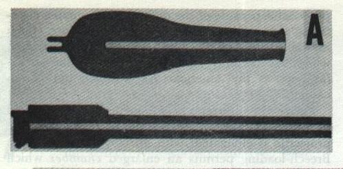
The difference in shape is very significant.
The figure also points out the main features of the contemporary gun
barrel.
Let us now consider these more closely.
1. At the breech end is a plug or breechblock which can be opened for
loading the gun.
Breechblocks take various forms; the illustration shows (as viewed from
above) the general structure associated with the sliding-wedge type used
in 5-inch mounts.
Early guns, except for a few custom-made small-arms weapons, were almost
invariably muzzle loaders; breech loaders were rarities.
Hence the silhouette representing the old gun shows no breech plug.
2. Just forward of the breech plug is an enlarged chamber to contain the
propelling charge.
3. The bore is rifled—a set of spiral grooves twists the projectile as
it moves toward the muzzle, so that it is spinning when it leaves the
gun.
Old guns as a rule were smoothbores.
In newer types of larger guns, the rifling is cut in a liner—a tubular
insert that can be replaced when worn.
Figure 5B7 C shows the rifling cut into the liner of an
8-inch turret gun of recent design. The liner reference marks are used
for aligning the liner in the gun tube.)
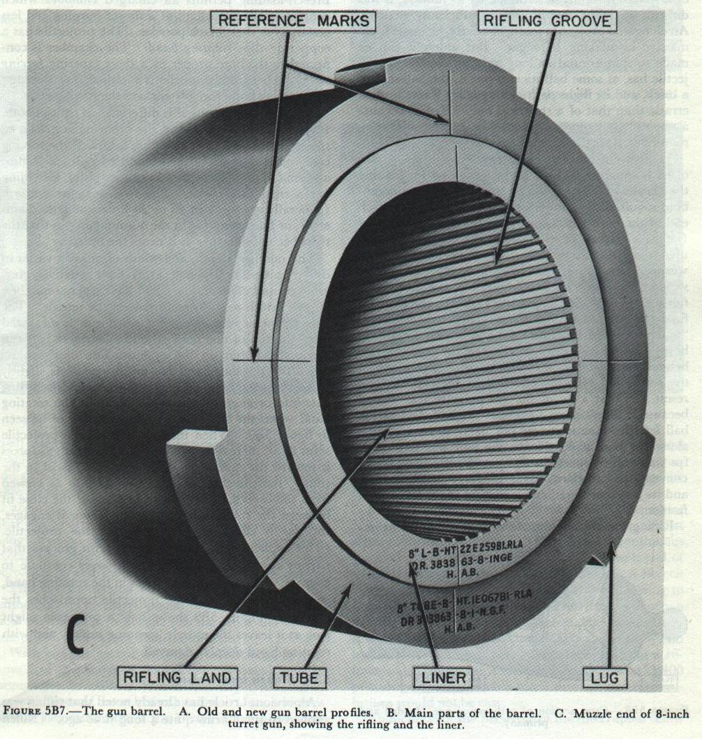
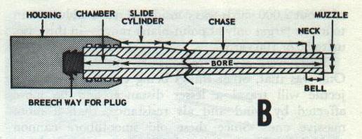
In other guns, the rifling grooves are cut into the barrel. 4. As
compared with early guns, the barrel walls are much thinner in modern
guns, and the taper is much less exaggerated. Improved propellants and
improved steels have together brought about this silhouette. Common
external features are pointed out in Figure 5B7 B. Many
guns have a bell at the muzzle, where the metal is made thicker to
discourage any tendency to split. Most modern weapons lack a bell, or
instead have lugs, which are utilized when the liner (see No. 3 above)
is replaced. (The lugs serve to anchor the tool used for pulling the
liner out. ) The thinnest part of the barrel, just aft of the bell, is
the neck. Then comes the tapering chase, followed by the slide cylinder,
which moves in a bearing in the slide during recoil. The after part of
the barrel is secured to the gun housing. In the conventional 5-inch
gun, the breechblock slides up and down in a grooved rectangular
breechway in the housing. Now consider what is between the exterior and
the interior surfaces of the barrel. —the steel itself. Looking at the
profiles of guns old and new (Figure 5B7 A and B), it’s
evident that although both taper from a wide breech end to a narrower
muzzle, the taper is much more drastic in the older weapon.
Superficially, this difference in silhouette may seem a small matter,
but it is actually very important. It indicates the revolutionary
developments in propellants and in metallurgy that differentiate the new
from the old. Consider what happens when the propellant in a gun is
ignited. As it burns, it turns to hot gas under terrific pressure—up to
60,000 psi in small guns, up to 40,000 psi in larger guns. As the
projectile moves along the bore toward the muzzle, the gas pressure goes
down. It follows, then, that the chamber wall should be the thickest
part of the gun barrel, with the taper from breech to muzzle reflecting
the decreasing gas pressure behind the projectile. However, when black
powder was the propellant, the chamber had to withstand the initial
shock of this propellant’s exceedingly rapid burning rate. Thus, before
the projectile was well along the bore, the propelling charge had
already developed its maximumpressure as a sudden shock, and the gas
pressure was falling rapidly. The breech had to be especially heavy to
withstand the shock, but the tube was short because the gas pressure
fell so rapidly. In modern guns using pyro or triple-base propellants,
the maximum gas pressure is developed far more smoothly, and declines
less suddenly. This is reflected to a great extent in the silhouette of
the modern barrel. The thinner barrel walls of modern guns are evidence
not only of more effective propellants but also of improved metallurgy
of the barrel. Before the ‘80’s of the last century, the surest way to
make the barrel of a gun withstand more pressure was to make it thicker.
But there were limits to this method. Then it was discovered that by
prestressing, it was possible to make a gun barrel more resistant to
internal pressure. The earliest method of applying this principle was to
heat steel ring-shaped jackets, or hoops, to high temperatures, then
slip them over the gun tube and allow them to cool. As the hoops cooled,
they contracted, until at the end of the process they were squeezing the
gun tube inside with a pressure of thousands of pounds per square inch.
Guns so constructed are known as built-up guns, and are still made in
sizes over 8-inch. About the time of World War I, the same principle was
applied to monoblock (one-piece) guns in the radial-expansion or auto
frettage process. In this process, a single steel gun tube whose bore is
slightly smaller than the caliber desired is filled with hydraulic
fluid. The pressure is then built up enough to enlarge the bore
permanently about 6 percent. When the pressure is released, the outer
layers of the tube tend to return nearly to their original dimensions,
while the inner layers, which have been considerably enlarged, tend to
maintain their increased diameter. The result is that the inner layers
of metal are severely compressed by the contracting force of the outer
layers, just as if a hoop or jacket had been shrunk on. In other words,
the tube is “self-hooped. ” The big advantages of the radial-expansion
mono-bloc gun over the built-up type are simplicity of manufacture and
comparatively low cost and weight. Because of the difficulty of working
on the single huge forgings required for guns over 8-inch, though,
larger weapons are still built-up. Or the two methods of prestressing
may be combined.
Rifling
Early guns were capable of hurling a projectile to a respectable range,
all things considered. Large cannon could heave an iron or stone ball at
a target a couple of miles away, and actually overshoot. But their fire
was so inaccurate that a gun capable of an extreme range of about 2,000
yards was considered reasonably certain to hit its target only at
point-blank range—in this case, up to 80 or 100 yards. There were
several reasons for this poor showing. One was that, other things being
equal, a light projectile will travel a lesser distance, and be more
affected by wind and air resistance, than a more massive one. Since
these old smoothbore cannon could fire only round shot (and the maximum
volume of a sphere is rigidly determined by its radius), it was
difficult to make the projectile sufficiently massive. An elongated
projectile could, of course, be made more massive by making it longer.
But unless it can be made to spin around its long axis, an elongated
projectile has, as some ballisticians put it, the ballistics of a brick,
and its flight path or trajectory is much more erratic than that of a
spherical one. Hence, because a smoothbore cannon cannot make its
projectile spin, round shot were the only alternative. There were other
reasons, too, for the inaccuracy of early gunnery.
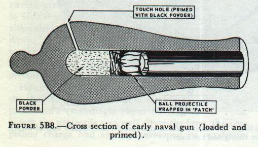
One standard method for loading the classical type of seagoing
muzzle-loading smoothbore required the gunner first to ladle into the
breech end of the bore a measured quantity of black powder (later, a
paper- of cloth-wrapped “cartridge” was used), and then to ram down
the bore the round shot wrapped in a fabric “patch. ” Since close
clearances would have made loading impossible, the shot was a fairly
loose fit. See Figure 5B8. When the gun was fired (by
lighting off a priming mixture which filled a “touch hole” leading
into the blind breech end of the bore), the patch was supposed to seal
the powder gases behind the loose-fitting ball projectile. But much of
the gas would blow by one side or the other. The result was that a lot
of the gas pressure was wasted because it didn’t serve to propel the
ball, and as the ball left the muzzle it was not likely to be
traveling along the bore axis. Hence the ball was slow (300 fps was a
likely speed, as compared with 2,700 fps in conventional modern naval
medium-caliber guns), and its trajectory predictable only in the most
general fashion. Rifling the oldtime muzzle-loading cannon was
impracticable because of the difficulty of ramming closefitting
ammunition down the length of the bore. Such ramming was possible only
in small arms (which is why rifled shoulder weapons were used by
infantry as far back as the American Revolution), but not in cannon.
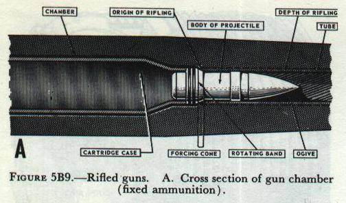
Figure 5B9 A illustrates how these problems are
solved in modern conventional naval guns. First of all, the projectile
is elongated, with an ogival forward end. Breech-loading permits an
enlarged chamber which contains more propellant of a slower burning
and less erratic type than black powder. The projectile has a copper
or alloy rotating band. The chamber is connected to the bore proper by
a short tapering forcing cone. When the projectile is rammed into the
gun, the rotating band forcibly engages the forcing cone.
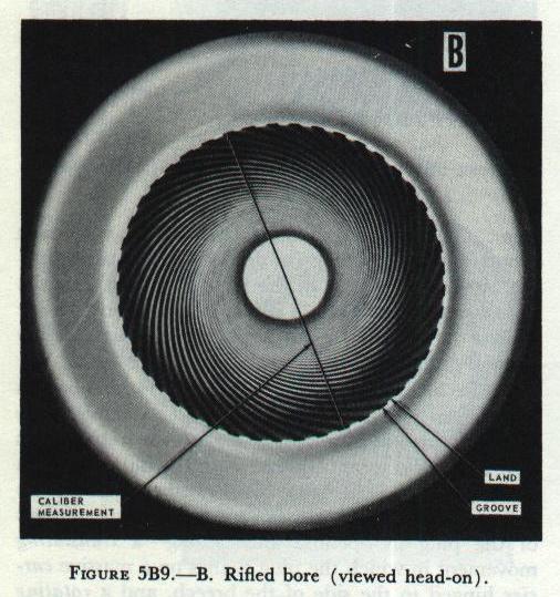
And the gun bore itself is different. It isn’t smooth. It is grooved
or rifled, and the grooving is helical or spiral. See
Figure 5B9 B. The rifling begins at the forcing cone
and continues to the muzzle. In all naval guns and small arms except
the .45 caliber pistol, the rifling has a right-hand twist. The twist
may be uniform (generally around 1 in 15 or 20 times the bore
diameter), or increasing (as in the 40-mm gun) so that the twist
becomes sharper as it nears the muzzle. The number, depth, and width
of grooves varies in different designs. Small arms have relatively few
grooves, and cannon (fig. 5B9) have a large number. Groove width may
decrease toward the muzzle.
The bore diameter or caliber of a rifled gun is measured from the top
of one land (the high surfaces between grooves) to that on the
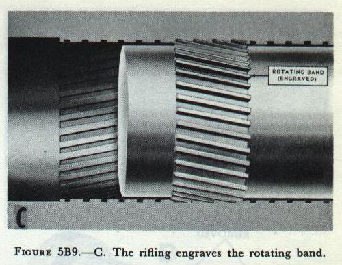
opposite side of the bore. Since the rotating band for the projectile
is slightly larger than the nominal gun bore diameter, the rifling
cuts into or engraves the softer metal of the rotating band when the
projectile is rammed, as can be seen in Figure 5B9 C.
When the gun is fired, the projectile spins at an increasing rate as
the propellent gas forces it toward the muzzle. (With right-hand twist
in the rifling, the direction of spin is clockwise as viewed from the
breech. ) Moreover, because of the close fit between the rotating band
and the rifling it engages, the gas is effectively sealed behind the
projectile. (This explains why rifling is made with grooves that
narrow toward the muzzle; the grooves continue to engrave wider and
wider notches in the rotating band, ensuring a tight fit as the
projectile approaches the muzzle. )
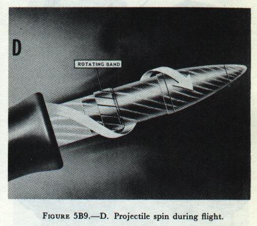
Figure 5B9 D shows how a projectile might look as it
leaves the muzzle, spinning rapidly and with rotating band deeply
engraved.
Breech Mechanisms
Rifling was applied to small arms quite a long time ago. Rifled small
arms were used in the American Revolution, and enabled American
sharpshooters to stand at a distance and pick off the redcoats, whose
smoothbore muskets were no match for the American rifles either in range
or accuracy. ) But it could not be applied in a practical way to
artillery, either seagoing or ashore. Ramming large-caliber ammunition
from the muzzle was excessively difficult if the projectiles fitted the
rifled bore closely, and the rifling was useless if they didn’t.
The key to making effective and practical rifled cannon lay in the
development of effective and practical mechanisms to permit loading from
the breech end of the gun rather than the muzzle. With but one
exception, all naval guns in present use in calibers 44)-mm and larger
use 1 of 2 general types of breech mechanism. One, which is used in bag
guns only, is the Welin interrupted-screw type. The other, used in
40-mm, 3-inch, 5-inch, and 6-inch guns, and in 8-inch turret guns for
case ammunition, is the vertical sliding-wedge type. Consider the
interrupted-screw type first. Interrupted-screw breech mechanism. The
screw is a widely used device for securing something against a heavy
thrust.
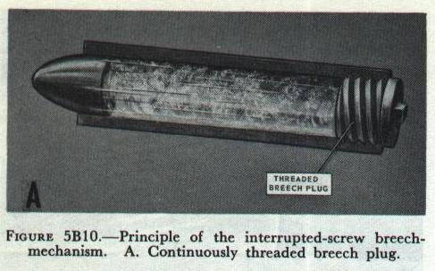
Figure 5B10 A shows how a continuous screw closure
might be used to seal the breech end of a metal tube to make a gun of
it. Such a breech closure or plug would of course require unscrewing
to open the breech after firing. The mass of such a device, designed
to withstand the 40,000 psi gas pressure developed in a typical
large-caliber cannon, would inevitably be considerable. (The breech
plug of a 16-inch naval gun, for example, weighs about 1,400 pounds. )
Turning such a screw through several revolutions would not be easy.
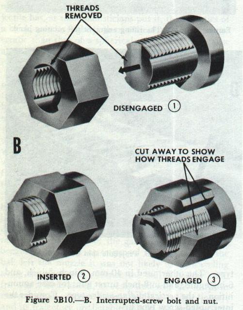
Application of the principle of the interrupted screw reduces the
number of turns required to a fraction of a revolution. If half the
threaded area is removed from a bolt (representing the breech plug)
and the nut (representing the breech or screw box), then it is
possible to insert the bolt Figure 5B10 B and engage
the two by turning the bolt 90° (3 in Figure 5B10).
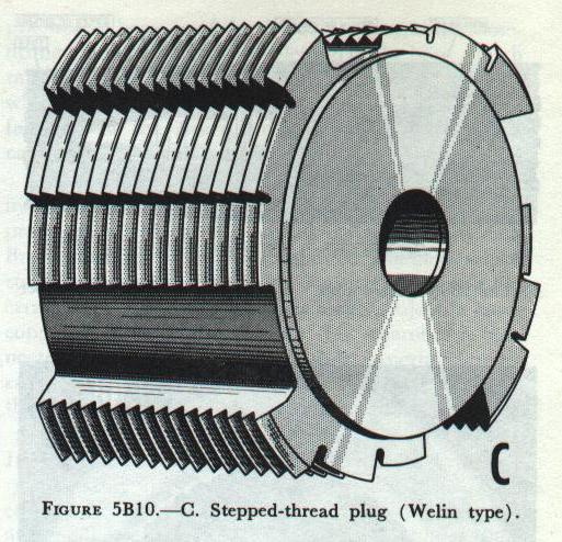
Figure 5B10 C Stepped-thread plug (Welin Type). The
disadvantage of this straightforward application of the
interrupted-screw principle is that half the threaded area must be
removed, and this reduces the “holding power” by reducing the amount
of thread area that can be engaged. This disadvantage is partly
obviated by the Welin stepped-thread breech mechanism. In this
arrangement, both plug and breech have steps. The steps are arranged
in groups, with each group of four ascending (or descending) steps
occupying one 90 degree sector. On the plug (Figure 5B10), the lowest step of each group is blank, and the others are
threaded. On the breech screw box the highest step in each group is
blank, and the others threaded.
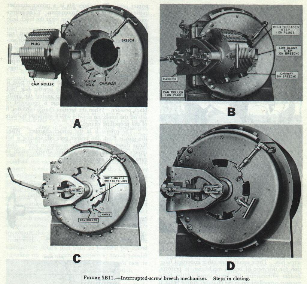
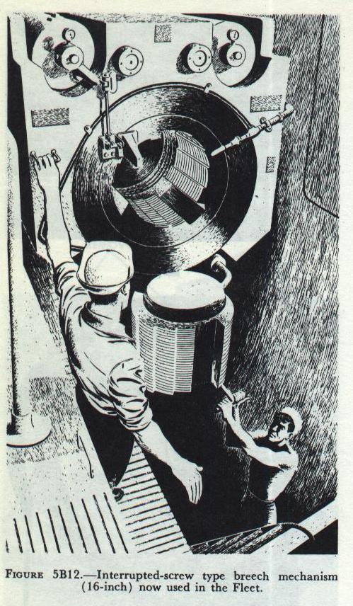
Figure 5B11 shows how an obsolete 14-inch breech
mechanism functions in closing. The principle is the same on
present-day 8-inch and 16-inch hag guns now in the Fleet, but in those
ships the plug swings in a vertical arc (as in
Figure 5B12) rather than a horizontal one. Note that
there are two distinct motions of the plug in opening and closing - a
translating movement in which the plug swings on a massive carrier
hinged to the side of the breech, and a rotating motion in which the
plug screws into the screw box. Both of these may occur together in
the final stages of dosing or the beginning of opening. Now follow the
breech-closing action as illustrated in Figure 5B11:
1. From its open position, the plug swings around toward the screw box.
As the plug moves in, each high threaded step of the plug fits into a
low blank step of the screw box (fig. 5B11). The high threaded steps on
the screw box fit into the low blank sectors of the plug. The other
threaded steps also clear each other in this position.
2. When the plug is well into the screw box, but has not yet begun to
rotate, a cam roller on the plug contacts a camway in the screw box.
(Figure 5B11 shows how the plug must rotate to engage
the screw box. )
3. During the last part of its translation into the screw box, the
plug’s cam roller engages the camway and the plug turns so that the
mating threads on box and plug engage.
Figure 5B11 shows the breech closed, locked, and ready
for firing. Notice the two great advantages of the Welin-type screw box
and plug:1. About 75 percent of the engaging surfaces of plug and screw
box are threaded. 2. The plug requires only about 27. 5 degrees of
rotation for full engagement and locking.
Compare these characteristics with the original bolt and nut, and you
can see the improvement. Welin-type breech mechanisms may have 3, 4,
or even 5 steps, counting the blank sectors. In most modem
installations, the plug swings vertically up into the screw box
(Figure 5B12) rather than horizontally as in the
14-inch breech pictured in Figure 5B11. Because of
the large size of the guns on which they are generally found,
interrupted-screw plugs are too heavy for unassisted operation by
hand. (As noted above, on a 16-inch gun the plug may weigh as much as
1,400 pounds. ) Interrupted-screw mechanisms for these large guns are
therefore generally fitted with air- or spring-powered devices to aid
the gun crew in operating them.
The discussion of the interrupted-screw type breech mechanism so far has
concentrated on the principles of operation of the engaging parts - the
plug and screw box. There remains one other important function for this
type of breech mechanism to perform. Besides withstanding the brute
thrust of the high-pressure propellent gas in the chamber during firing,
it must also prevent leakage of the burning, toxic gas into the turret
or mount. It does this by means of an obturator or sealing device - the
DeBange gas-check system.
The DeBange gas-check system is
used in all United States Navy bag guns. Its main parts are the
mushroom, gas check pad, split rings, and gas check seat.
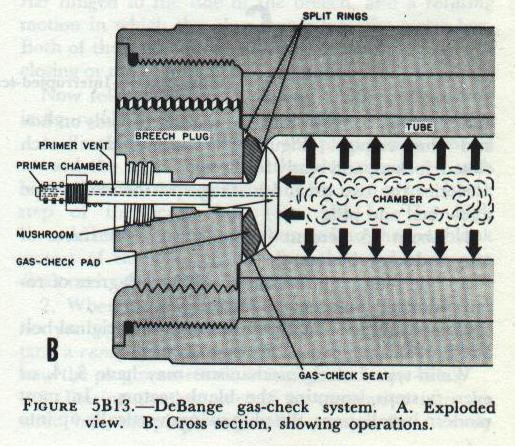 Figure 5B13
 A shows a typical gas-check assembly.
The
biggest component is the mushroom. (In a 16-inch gun it weighs 220
pounds.) It consists of a large flat steel head at the forward face of
the plug, with a long steel stem extending through a hole in the plug
and protruding from its rear face. Through the center of the stem and
head passes a hole called the primer vent. The primer fits in a primer
chamber in the after end of the mushroom stem. (The-primer vent does for
the modern bag gun what the touch hole did for its ancient
counterpart.)
Between the mushroom head and the forward face
of the breech plug, and bearing against a smooth section of the breech
chamber called the gas-check seat, is the gas-check pad. This is a thick
flat resilient doughnut-shaped disc of plastic, whose outer and inner
edges are protected from wear by steel split rings.
The
system works this way:
1. When the gun is loaded and the
breech plug is closed, the ignition charge in the powder bag (not shown
in
Figure 5B13 B) is right up against the mushroom
head. (The ignition charge is composed of black powder. When the
ignition charge explodes, it sets off the smokeless powder which
comprises the bulk of the propelling charge.)
2. The primer
is in the primer chamber. When the gun is fired, the primer goes off,
sending a hot flame down the vent in the mushroom stem. That ignites the
black powder ignition charge, which in turn sets off the smokeless
powder.
3. As the powder burns, the expanding gases push hard
against all sides of the breech chamber, the projectile, and the
mushroom head. The only thing that can yield is the projectile, which
begins to move up the gun bore.
Meantime the pressure goes
higher and higher up to 40,000 psi until the projectile is fully under
way, when the pressure tapers off.
4. As the pressure
increases, it shoves the mushroom head hard back against the gas-check
pad. The pad expands against the gas-check seat, effectively sealing the
breech against the escape of gas. And note this feature of the device -
the greater the gas pressure, the harder the mushroom compresses the pad
against the gas-check seat. Vertical sliding-wedge breech mechanism. The
interrupted-screw type of breech mechanism has its advantages. Since it
has its own obturator mechanism, it can use propelling charges in silk
bags which are consumed in firing, and once the bore is cleared of
residual gases and burning fragments, the next round can be loaded
without requiring extraction and disposal of the used container for the
fired propelling charge. It can also be used (though the U. S. Navy has
no guns of this type in active service at the present time) to fire case
ammunition.
But this kind of breech mechanism also has
disadvantages. One is really to be ascribed particularly to the nature
of the ammunition itself. Because of the fire hazard, a crewman must
inspect the chamber after each round fired to ensure that it is safe to
load the next round. This slows the rate of firing. More important, this
kind of breech mechanism is complex in operation. Coupled with the
number of separate ammunition details that must be handled per round
(totaling up to 8 - primer, projectile, and 6 powder bags), this type of
breech mechanism is not easy to adapt to automatic or semiautomatic
operation.
For this reason, guns 40-mm and up, of late
designs, use a breech mechanism that works on a completely different
principle - the sliding-wedge breech mechanism. This uses a sliding
element to block off the breech opening. The sliding breechblock may
move either horizontally or vertically.
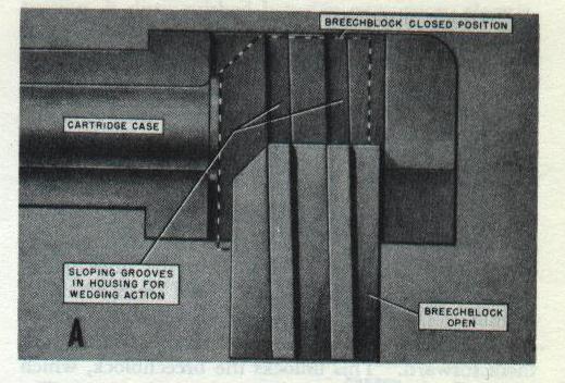 Figure 5B14 A
 shows in simplified form the elements of
a vertical sliding-wedge breech mechanism as it looks from the side,
with the breechblock or plug in its lowered (open) position. The dotted
outline represents the breechblock in its raised (closed) position.
Notice that the grooves in which the plug can slide up and down are not
exactly vertical; they’re slanted slightly forward. It is clear that in
its open position the plug is noticeably aft of its closed position. Or,
in other words, in rising to the closed position, the breech-block moves
forward as well as upward.
The effect of the breechblock’s
forward movement as it closes is to wedge the cartridge case into the
gun chamber (hence the name sliding-wedge breech mechanism).
The
method of obturation used in this type of breech mechanism depends on
the cartridge case for sealing effect. There is no sealing device
incorporated into the breech mechanism.
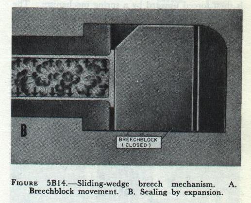 Figure 5B14 B
 shows what happens when the gun fires. As
the propelling charge burns, the hot powder gases expand against the
sides of the cartridge, which in turn expand against the smooth walls of
the chamber and against the breech-block. Since the cartridge case
tightly seals off the entire length of the chamber, the gases can escape
only forward, driving the projectile. None can escape through the
breech. This is sealing by expansion. But after the gun fires, the
chamber is not clear. The cartridge case is not designed to disappear
with the burning propelling charge, and it must be removed from the
chamber before a new round can be loaded.
Therefore all guns
with sliding-wedge breechblocks have one or a pair of extractors as part
of the breech mechanism. In 40-mm, 3-inch, and 5-inch guns the
extractors are mechanically operated by breechblock movement.
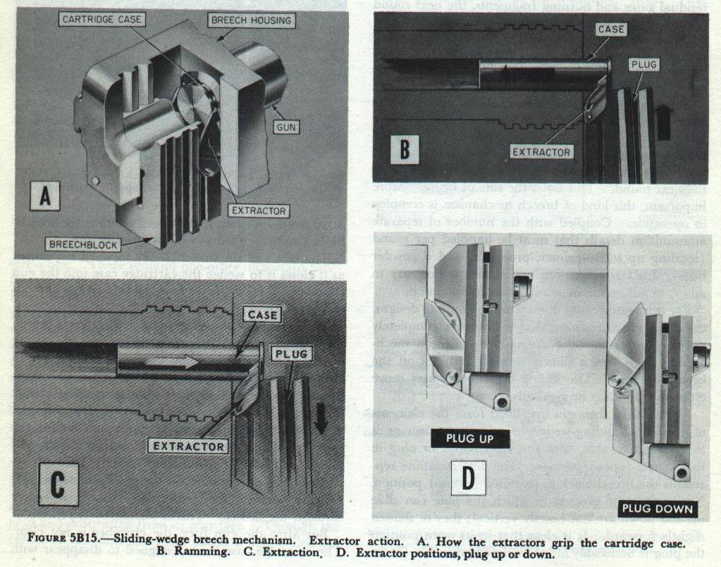 Figure 5B15
 shows several views to clarify their
functioning. When the breechblock is down (open) the extractors are
pulled back. In these guns the extractors perform the dual function of
locking the breehblock down and extracting the case. As a fresh round of
ammunition is rammed into the chamber, the rim of the cartridge case
engages the extractors, and pulls them forward. This unlocks the
breechblock, which is then forced upward by a spring mechanism. The
round is chambered, the breechblock moves upward, and the extractor tips
move forward in a coordinated group of movements. When the breechblock
is fully closed, it has forced the round fully into the chamber, and the
extractor tips have seated in recesses in the housing.
After
the gun fires, the breechblock is opened by camming action. As the
block drops, the extractors retract. They haul the fired cartridge case
out of the chamber and catapult it to the rear into the slide. At the
extreme of their rearward movement, they lock the breechblock down until
the next cartridge case again pulls them forward to unlock the
breechblock.
Figure 5B15 shows the type of breech mechanism used in
conventional 3-inch and 5-inch guns. In 40-mm guns the sequence of
operations is similar, but the extractors are pivoted on a spindle, and
lock the breechblock down with a pair of hooks. In 3-inch and 5-inch
breech mechanisms the extractors are not pivoted, but rock back and
forth on their forward curved surfaces, which bear against the gun
housing. The movement of each extractor is controlled by two lugs; the
inner lug engages a camming groove in the breech-block, and the outer
one oscillates in a small curved groove in the housing. It is also
noteworthy that in 3”/50 guns equipped with power loaders the
breech-block-locking function of the extractors merely supplements the
normal functioning of another locking mechanism (described in another
chapter). But, regardless of the method of locking, the extractors
unlock the breechblock when they are moved forward by the cartridge case
being loaded.
In contrast to the sliding-wedge breech
mechanisms described above, which are operated through mechanical
camming and spring action when the gun housing moves backward and
forward in recoil and counter-coil, the breech-mechanism in 6-inch and
8-inch case guns are operated hydraulically.
The descriptions
above do not apply to the very newest designs of 3-inch and 5-inch gun
mechanisms with sliding-wedge type breech mechanisms.
Bolt-type breech mechanisms. The sliding-wedge and
interrupted-screw types of breech mechanisms are not used in guns 20-mm
and smaller. These use variants of the bolt principle. The bolt is a
breech-block which moves in line with the bore axis - forward to close
the breech, and to the rear to open it.
In so-called
bolt-action weapons like the old M1903 rifle (the famous “Springfield”
of World War I) the bolt is operated by hand.
In gas-operated
weapons like the Browning automatic rifle M1918A2 (the “BAR”) or the Ml
rifle (“Garand”) the bolt is cammed to the rear by a piston actuated by
a small amount of propellent gas diverted from the barrel while the
bullet is moving through the bore. Spring action forces the bolt forward
to ram the next round home.
In recoil-operated weapons like
the Browning machine guns, a complex of mechanical parts is forced to
the rear to varying distances by recoil, and is then driven forward by
springs to reload and fire the next round.
In
blowback-operated weapons like the 20-mm AA gun and the Thompson or M3
submachine guns (“Tommy” guns) the bolt is pushed back, when the gun is
fired, by gas pressure in the chamber, and a spring mechanism afterward
forces it forward to ram the next round home.
Aircraft
machine gun designs use all three of these actuating forces (gas,
recoil, and blowback).
Gun Barrels and Interior Ballistics
The preceding has already defined a gun as a tube designed to discharge a
projectile at high velocity by the gas pressure produced by a propellant
in the tube. Commonly, the term gun applies to the entire assembly of
which the barrel is but one part.
The gun, tube, or barrel
designates the gun tube only, and not the remainder of the gun assembly,
which includes, in addition, the mount and other parts.
This
concerns the gun barrel construction and maintenance, and with interior
ballistics - what happens inside the gun when it is fired.
Elements
of Gun Design and Maintenance
Modern requirements for gun
power
Present requirements for guns demand muzzle velocities of
from 2,500 to 3,500 fps. Lower velocities give less striking energy. More
important still, a projectile fired at low velocity would describe a curve
so high in the air, for long ranges, that hits could not be made unless
the range were known with great accuracy. Since the accurate determination
of range is a critical problem in naval gunnery, the high-power gun is a
necessity. High velocity of a projectile is produced, of course, by high
pressure upon it while traveling through the bore.
A gun may be
considered as a tube designed to withstand a given pressure from within.
In constructing such a tube, we must first consider what pressures it will
have to withstand at the various points of its length, and then make it
strong enough to insure perfect safety. The bore should also be of such
material as to stand the wear and tear of firing a large number of rounds
without being so damaged by expansion or abrasion as to interfere with the
shooting. Stresses in a gun cylinder
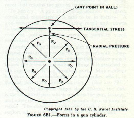
Considering a gun only as
a cylinder, we find that the two principal stresses (Figure 6B) to which
such a cylinder is subjected upon the explosion of a charge are:
1.
A circumferential or tangential stress or tension, coupled with a radial
stress, tending to split the gun open longitudinally.
2. A
longitudinal stress tending to pull the gun apart in the direction of its
length.
Experiments have shown that the greatest stress on the
metal of the gun is the tensile stress set up in the direction of its
circumference by powder gas pressure. In addition, the gun also
experiences a longitudinal stress of relatively small value. If this
longitudinal stress may be considered constant (and in guns it may be so
considered without great error) we may lay down the first of “Lame’s
laws,” as follows:
At any point whatever, in a cylinder under
fluid pressure, the sum of the tangential tension and the radial pressure
varies inversely as the square of the radius.
This law says, in
effect, that in a simple hollow cylinder under internal pressure, points
in the metal close to the bore experience a large proportion of the
stress, whereas those at a greater radius experience only a small
proportion. This means that in a simple hollow cylinder composed
throughout of metal of homogeneous physical properties, we soon reach a
limit beyond which any thickness of wall aids but little in enabling the
cylinder to withstand pressure.
Hence a modern gun would not be sufficiently strong to withstand the
required pressure if made of a single simple hollow cylinder, however
thick. But the gun must be built on a principle which will enable it to
withstand more internal pressure than could be withstood by the simple
cylinder type of construction. The problem is to make the outer layers
take a proper proportion of the stress. In one modern solution to the
problem, the gun is constructed of layers of metal. The layers nearer
the bore are held under an initial compression by the tension of the
outer layers. Thus, when the gun is fired, the inner layers must first
be expanded sufficiently to remove the initial compression before they
begin to experience a positive tension or stretch, while the expansion
is continuously resisted by the tension of the outer layers.
Properties of Gun Steel
Before considering the construction of a gun according to this
principle, it will be necessary to examine some of the properties of gun
steel which have not yet been considered.
Gun steel is
elastic within limits: thus, if a stress is applied so as to set up a
strain (deformation or change in dimension) not exceeding the elastic
limit of strain of the steel, then the steel will return to its original
shape and dimensions when the stress is removed. It is then said to have
been worked within its elastic range. However, when the elastic limit of
strain has been reached, if the stress is increased the steel will yield
rather suddenly and suffer a comparatively large strain without further
increase in stress. Thereafter increase in stress will still further
increase strain. The steel is now being worked in its semiplastic range.
(If the stress is still further increased the strain will go beyond the
semiplastic range and the steel will give rapidly and fracture, even
with decrease of load.) The important point is that the steel has now
received a permanent set or deformation. Nevertheless, it will attempt
to return to its former dimensions when the stress is removed. In other
words, it has suffered a deformation that is permanent but elastic.
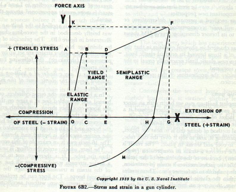
These
properties of gun steel are plotted in
FIGURE-6B2, in
which the ordinates, measured along OY, represent the stresses applied
to a test piece, and the abscissas, measured along OX, represent the
corresponding strains set up. The curve is drawn only to show tension
stresses causing extension strain in the steel, but it could be shown
that the steel behaves similarly under compression stresses causing
compressive strains.
As the stress is raised from 0 to A, the
steel is strained by the amount OC. If the load is increased slightly,
the steel yields suddenly and suffers the additional strain CE at
practically constant load. A further increase in the load to K causes an
additional strain EG. The behavior of the steel thus far is represented
by the curve OBDF.
If the load is now removed, the curve is
seen to return, not to the origin but to the point H, the line FH being
about parallel to OB. The steel has taken the permanent deformation, or
strain, OH but still has elastic properties, as is shown by the decrease
in strain from G to H upon removal of the load. HG is somewhat larger
than OC. If the same test piece is again stressed, a stress equal to OK
will be required to strain it by the amount HG; for purposes of such a
second stress, H may be considered to be at the origin.
From
the above, it may be seen that the steel has acquired two important new
properties:
(1) It has received a permanent deformation, or
strain, and will resist a compression stress tending to compress it to
its former dimension (curve HM shows this action).
(2) It has
changed its physical qualities in that the application of a stress
beyond its original elastic limit, has given it a new elastic limit
practically equal to the stress it has sustained.
Now
consider the application of this principle to gun construction.
Built-up Guns
In the simplest built-up gun we begin with an inner steel tube of outer
diameter d, and place around it a cylindrical jacket of inner diameter
d-s. s is small— on the order of 0.01 in.; s is called the shrinkage.
The
usual method of doing this is to heat the jacket, thereby expanding it,
and to slip it over the cold tube, allowing it to cool and shrink in
place.
The result is that the tube receives a strain in
compression (negative extension), because of the shrinkage of the jacket
upon it, while the jacket receives a strain in extension, being unable
to shrink to its former size.
These strains are well within
the elastic limit of strain of the steel.
We have here,
then, not an initially unstrained steel, but a compound cylinder of two
members, the inner of which has an initial strain in compression
(negative) and the outer an initial strain in extension (positive).
When
powder gas pressure (stress) is applied in the bore of such a compound
cylinder, the pressure must first expand the tube enough to remove the
initial strain of compression before it can continue the expansion
toward the elastic limit of extension of the tube.
Such
expansion is continuously opposed by the jacket, which is pressing
inward. This action may be stated in the following principle:
If
any pressure be applied to a compound cylinder, the strain at each point
will be the algebraic sum of the strain at the point before the pressure
was applied and the strain which the same pressure could cause at the
corresponding point in a simple cylinder, of the same dimensions as the
compound one.
In a compound cylinder, according to this rule,
the inner layer receives less strain in firing than would be received by
the corresponding layer in a simple cylinder, for the original
compression must first be overcome before any positive strain
(extension) can be introduced.
Correspondingly, the outer
layer receives more strain than it would in a simple cylinder plus the
original strain in extension that it receives in construction.
The stress felt by the different layers of the gun is then
no longer inversely proportional to the square of the radius according
to Lame’s law, but instead is more evenly apportioned among the layers
of metal.
This principle is applied in the built-up gun.
Figure 6B3 The principle of prestressing by shrinkage
has its limits of application, however.
Regardless of
whether strains are set up by firing or by prestressing (shrinkage),
the following limiting principle applies:
No fiber of any
cylinder of a built-up gun must be strained beyond the elastic limit
of the metal of that cylinder.
In a built-up gun, the outer
cylinders, or hoops, are heated and assembled one at a time on the
tube.
As the hoops cool, they shrink, and tightly grip the
cylinders within them.
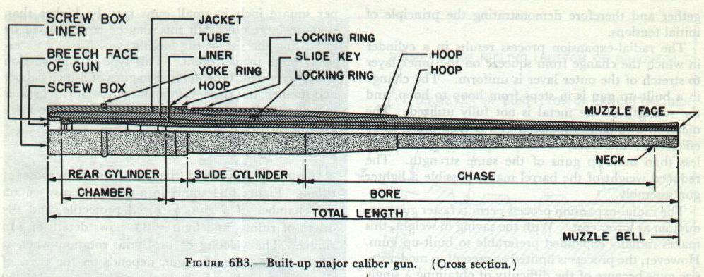
The locking rings are then added to prevent longitudinal movement of
the hoops.
After the hoops and locking rings are assembled
on the tube, the entire assembly is heated and shrunk on a liner.
The 16-inch gun is an example of this construction.
The
liner, which carries the rifling, is usually thinner than the tube. It
is, therefore, not to be considered a major strength member, since all
but a small part of the strain is transmitted through the liner to the
tube and hoops.
The liner can be replaced when the rifling
has worn down, without sacrificing the other parts of the barrel which
have a much longer service life.
The assembled barrel forms
a cylinder within which high pressure is developed as the charge
explodes.
The effect of the pressure is greatest on the
inner cylinder, and diminishes rapidly as it proceeds outward.
If the outer hoops were assembled over the tube without
shrinkage, they would be subjected to less strain than the tube and
the strength of gun would be little greater than the strength of the
tube.
However, the shrinkage of the hoops squeezes the
tube, at the same time stretching the hoops.
The safe
pressure of explosion can then be increased, for it must overcome the
squeeze before it can stretch the tube.
The shrinkage is so
calculated that each hoop carries a share of the strain.
Radially
expanded guns
A gun made from a single cylinder which has
been subjected to a radial-expansion process is called a radially
expanded monobloc gun.
In this process the gun forging is
bored to a diameter somewhat less than the finished dimension, and
turned down on the outside to something greater than its finished
diameter.
Hydraulic pressure is then applied to the bore.
By Lame’s law the metal at various points through the wall
of the gun will experience stresses which are inversely proportional
to the square of their radii.
The pressure in the bore is
increased in steps, until a thin, indefinite layer of metal nearest
the bore is brought to its elastic limit of strain.
At
this time all the other (imaginary) layers of metal in the forging are
also strained, but all within their elastic limit, and the amount of
strain decreases regularly as we consider layers of the metal more and
more remote from the bore.
The pressure is now increased so
that the bore layer is strained beyond its elastic limit, the layer
next outside the bore layer is brought just to its elastic limit, and
the tension in all the other layers is increased.
Still
further increase of pressure increases the permanent strain in the
bore layer ( which is now being worked in the portion of the curve
BDF, (Figure 6B2), strains the second layer beyond its elastic limit,
brings a third layer up to its elastic limit, and increases the
tension in all the other layers.
The increase in pressure
is continued until the outside layer of metal just reaches its elastic
limit of strain, and this pressure is held for a time.
This pressure is considerably greater than the pressure
which the gun will be called upon to withstand when fired.
When
the pressure is removed and the metal allowed to return to a state of
rest, the physical condition of the forging is as follows:
1.
The bore layer, which has experienced the greatest stress and
therefore received the greatest permanent strain, is pressing outward
upon the second layer, for it tends to be larger than the second
layer.
Having received the greatest stress, it has a
greater permanent-and-elastic limit than the second layer, and a
greater elasticity.
2. Conversely, the second layer, having
received slightly less stress, is strained slightly less, has less
elasticity, and is pressing inward upon the first layer.
3.
Continuing outward, the third layer bears the same relation to the
second layer as the second does to the first, and so on.
The
net result is that the inner layers are being pressed upon by the
outer layers, and receive a strain in compression, as in the curve HM,
Figure 6B2, but they resist this pressing inward by pressing outward,
and thereby place the outer layer in a state of tension.
We then have a gun constructed by a process of selfhooping
(autofrettage), made as if composed of an infinite number of
infinitely thin hoops shrunk together and therefore demonstrating the
principle of initial tensions.
The radial-expansion process
results in a cylinder in which the change from squeeze on the inner
layer to stretch of the outer layer is uniform.
The change
in a built-up gun is in steps from hoop to hoop, and the strength of
the metal is not fully utilized.
The metal in a radially
expanded gun is used much more efficiently; therefore, radially
expanded guns weigh less than built-up guns of the same strength.
The reduced weight of the barrel makes possible a lighter
gun assembly.
The radial-expansion process permits faster
gun production at lower cost.
With the saving in weight,
this makes radially expanded preferable to built-up guns.
However, the process is limited at present to
moderate-size guns because of the difficulty of obtaining a single
forging large enough for those of major caliber.
Typical
monobloc barrels are found in the 5”/38 caliber guns and the 6”/47
caliber guns.
Combination guns
The built-up and
radially expanded methods may also be incorporated in a single gun.
Thus the difficulty of obtaining a single forging big enough for the
larger guns can be overcome. The 8”/55 caliber gun, for example, has a
jacket shrunk on a radially expanded tube.
Simple one-piece
guns
Many small guns such as the 40- and 20-mm are made
from a single steel forging which requires neither radial expansion
nor hoops. The pressures developed per square inch in small guns may
be higher than those in large guns, but this may be compensated by
increasing the size of the forging, which is not excessively large in
any event. This type of construction is, at the present time, limited
to guns of 3-inch caliber and smaller; but the development of steels
with greater metallurgical strength may make it applicable to large
guns in the future.
Rifling
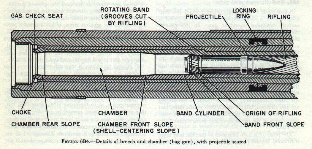 Figure 6B4
 shows in a detailed cross section the
chamber of a gun, a seated projectile, and the origin of rifling, and
Figure 6B5 shows details of gun rifling. The velocity
of projectile rotation when it leaves the muzzle of a gun depends on the
twist of the rifling and the velocity of the projectile. A 16”/50
projectile turns at about 4,000 rpm when it leaves the muzzle, and a
40-mm projectile turns at about 40,000 rpm.
In guns 5-inch
and smaller, rifling is cut into the gun tube’s bore. Larger guns may be
fitted with tubular loose liners, which can be replaced with relative
ease when the rifling is worn out. The rate of rifling wear tends to
increase with caliber.
Differences in construction between
case and bag guns
Nowadays only large guns (8-inch and up)
use bag ammunition. Hence bag guns are generally of the built-up type,
while a case gun may be monobloc or built-up, depending on size. Other
differences in construction between case and bag guns are concerned only
with the breech structure.
The breech end of a case gun
generally terminates in an interrupted-screw thread which meshes with a
similar thread in the gun housing.
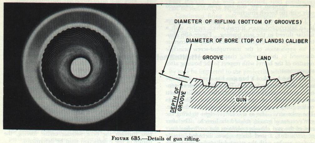
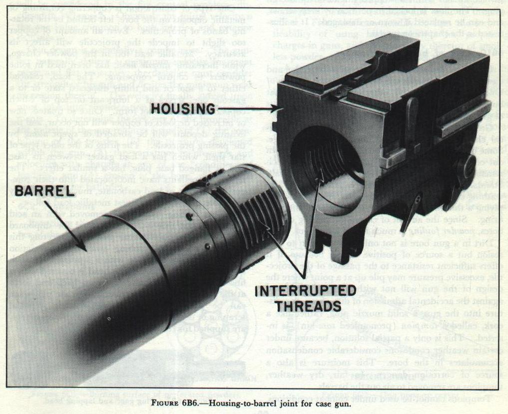 Figure 6B6
 illustrates a typical arrangement, which is
easy to recognize as an application of the interrupted-screw principle
discussed in the preceding chapter. A key prevents rotation of the
barrel with respect to the housing after engagement.
The
breech end of a bag gun has a yoke, a massive metal ring, surrounding
it. The yoke provides a connection between the barrel and other
recoiling parts and the recoil and counterrecoil systems. Shoulders on
the gun prevent movement with respect to the yoke. The yoke serves also
as a counterweight to bring the gun’s center of gravity toward the
breech. The after end of the gun chamber contains the screw-box liner or
screw box, a steel insert whose threaded interior surface meshes with
the stepped thread of the breech plug. The liner is locked in position
by keep screws, and can be replaced if worn or damaged. Care of bore and
chamber
Great heat, great pressure, and complicated chemical
changes accompany the burning of the charge. Some but not all of the
residue of the burning is blown out of the muzzle after the projectile.
That which remains in the gun is in the form of a corrosive salt.
Standard procedure is to remove this “fouling” by washing out the bore
with a hot soda solution and applying a thin film of oil before securing
until the next firing. Since the advent of chromium plating of gun
bores, powder fouling is much less of a problem.
Dirt in a
gun bore is not only an invitation to corrosion but a source of positive
danger because, if it offers sufficient resistance to the passage of the
projectile, excessive pressure may pile up at a point where the design
of the gun will not withstand it. To guard against the accidental
admission of dirt, spray, or moisture into the gun, a solid muzzle plug,
rather like a cork, called a tompion (pronounced tom-kin), is inserted.
This is only a partial solution, because under certain weather
conditions considerable condensation accumulates in the bore. This
moisture is also a source of corrosion danger. In fair, dry weather,
tompions are removed to air out the barrels.
Tompions cannot
be used under combat conditions, because of the possibility of one
inadvertently remaining in a gun when firing. However, dirt and water,
especially salt water, must be kept out of the gun; so canvas, or in the
case of small calibers, plastic, muzzle covers are used. In an
emergency, the projectile can be forced through such covers without
bursting the barrel. This procedure is, of course, subject to certain
limitations. Projectiles with supersensitive nose fuzes cannot be fired
through muzzle covers of any sort. In cold-weather operations, when
canvas covers may become ice coated, they should be removed before
firing.
More immediately dangerous than corrosion or dirt is
metallic constriction of the bore. Before and after each firing, barrels
are tested for this condition with a plug gage, which is a steel
cylinder accurately machined to slightly under the diameter of the bore.
If at any time it is discovered that the plug gage will not pass through
the bore without undue forcing, the nature of the constriction must be
determined.
One type of constriction is coppering consisting
of metallic deposits on the bore, left behind by the rotating bands of
projectiles. Even an amount of copper too slight to impede the
projectile will affect its accuracy. Metallic lead foil in the powder
charge, while increasing muzzle flash, has been used in some powders to
control coppering. The lead, reduced either to a molten and thinly
dispersed state or to a gaseous one, serves as a lubricant on top of
which copper deposits will not form. Once so treated, new or increased
deposits of copper will not occur, and the existing deposits will be
abraded or swept along by the passing projectile. The firing of the
older type of star shell, which has a lead gasket between its base and
its flanged base plug, has a similar effect. The newest propellants have
incorporated into their composition a trace of lead carbonate, much more
readily reducible than even the finest metallic lead foil.
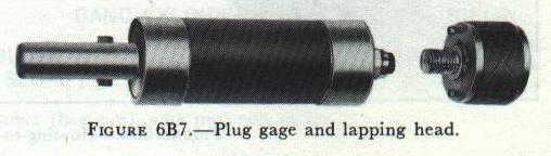
Copper fouling may also be removed with an acid treatment, but this is
not authorized for shipboard use. Approved mechanical means for meeting
this condition consist of rubbing away the constriction with a wire bore
brush or with a lapping head such as shown in
Figure 6B7. The head is covered with a fine abrasive material and is drawn back
and forth at the location of the constriction until the plug gage can be
passed through without forcing. Special scraping or decoppering heads,
fitted with steel blades, are supplied for certain guns. Steel
constriction also occurs in built-up guns. The friction of the
projectile on the bore tends to drag the liner along with it, which
tendency is resisted by the shoulders of the liner and the tube. With
continued firing, the shoulders of the liner tend to override those of
the tube, thereby forcing the walls of the liner inward. As with
coppering, steel constriction can be removed by lapping and
polishing.
Continued firing may also elongate the liner and
cause it to protrude from the muzzle. This is not a serious condition.
When the extension amounts to as much as half an inch, it is simply
cutoff.
