| NAVAL ORDNANCE AND GUNNERY, VOLUME 2 CHAPTER 23 AIRCRAFT FIRE CONTROL |
| HOME INDEX Chapter 23 Aircraft fire control A. Introduction B. Aircraft gunnery C. Aircraft weapon systems D. Theory of horizontal bombing E. Other bombing problems F. Rocketry |
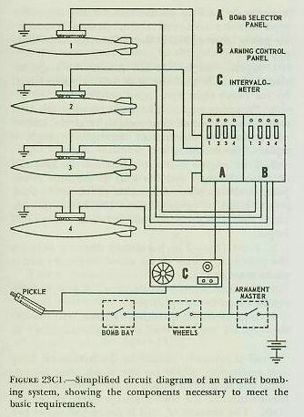
| C. Aircraft Weapon Systems 23C1. General Aircraft are used to deliver a large variety of destructive ordnance, including bombs and depth bombs, rockets, projectiles, mines, torpedoes, and guided missiles. To carry this ordnance safely and to deliver it effectively, the aircraft must be provided with a carrying, arming, and launching system that is compatible both with the weapons and with the aircraft itself. 23C2. Weapon compatibility In any weapon system, the components must be exactly adapted to each other if the system is to function effectively. For example, the carrying lugs of bombs must have exactly the same spacing as the hooks on the bomb rack designed to carry them; and the carrying lugs of rockets must be exactly shaped to fit the rocket launcher. Securing the necessary cooperation between the manufacturers of airframes, armament, and munitions, is one of the most important responsibilities of the material bureaus in Washington. 23C3. Bombing system A bombing system consists of suspension, arming, and releasing equipment. Bombs are armed and released by mechanical devices, which may be operated either electrically or manually. Bombs may be suspended from racks mounted on the wings or fuselage, or supported on shackles within the bomb bay. A bomb rack is a permanent or semipermanent structure rigidly bolted to the aircraft. It may or may not be enclosed by a streamlined housing called a pylon. Bomb shackles are nonrigidly suspended from attachments in the aircraft structure. They are used primarily in bomb bays that employ vertical stowage on side rails. When a bomb is released, its shackle swings out of the way, providing clearance for the bomb above. Bomb racks contain integral release and arming devices; bomb shackles depend on other units for control of arming and release. Bomb racks are carefully designed for compatibility with the bombs they are intended to carry. Bombs are. suspended by two lugs spaced either 14 or 30 inches apart. The rack must be strong enough to support the weight of the bomb (from 100 to 2,000 pounds), and to resist the additional stress that results from combat maneuvers. During violent maneuvers, this stress may be many times the weight of the bomb itself. The intervalometer generates electrical impulses that actuate the bomb release units. It may be set fore either selective or train release of bombs. When set at SELECTIVE, the intervalometer generates a single release impulse each time it receives an impulse from the bombardier’s firing switch or from the bomb sight. When set at TRAIN, the intervalometer provides a series of evenly spaced impulses. The number of impulses (up to 50), and therefore the number of bombs dropped, is controlled by a dial setting. The impulse frequency can be varied from 2 to 20 per second; it is controlled by matching two dial scales, one of ground speeds and one of distances between the impact points of successive bombs. When the desired spacing is matched with the actual ground speed of the aircraft, a small computing unit automatically sets the proper impulse frequency in the intervalometer. The bomb-rack release is a mechanical device that releases the bombs by disengaging the bomb-rack hooks from the bomb lugs. The mechanical release is operated by solenoids, which are actuated by impulses received from the intervalometer by way of the bomb selector panel. Operation of the release mechanism is controlled by a mechanical actuator, which may be set to any of three positions: ELECTRICAL ARMED RELEASE. (normal operation), SAFE, and MECHANICAL SALVO UNARMED RELEASE. When the actuator is set at safe, no bombs can be dropped. The mechanical salvo position makes it possible to jettison all bombs without arming them. The station distributor is a specially designed relay switch that distributes impulses from the intervalometer to selected stations in the bomb-release system. Its operation may be controlled by setting a knob pointer to any of 32 dial positions, each of which corresponds to a bomb station. Bombs at any station, or at all connected stations, may be released in train by setting the knob to the dial position corresponding to the first station in the desired train release. Bomb-arming controls provide for selective arming of bombs. Bombs may be provided with both nose fuzes and tail fuzes, either of which may be armed, as desired. Fuze arming is initiated when an arming wire is withdrawn from it. In the arming control system, a solenoid-operated clamp holds the desired arming wire, so that it will be withdrawn from the fuze as the bomb drops. The wire in any fuze that is not to be armed is allowed to fall with the bomb. The master armament switch controls the operation of the entire system; when it is open, no bombs can be dropped. Some installations may be provided with either or both of two safety switches; one of these disables the bomb release system when the bomb bay doors are closed, the other when the wheels are down. Figure 23C1 is a simplified circuit diagram of a typical aircraft bombing installation. |
 |
 |
| 23C4. Rocket systems An aircraft rocket system, like any weapon system, must be exactly adapted to the requirements of the ordnance it is designed to carry and launch. Aero 14A and Aero l4B will serve as examples of typical rocket launchers. These are fixed pylon units installed under the wing of the aircraft; the latching, release, and arming mechanisms are contained within an aluminum fairing that bolts to the under side of the wing over a rubber gasket. Each unit is designed to carry and launch 5-inch HVAR rockets, and all 2-lug 14-inch diameter bombs, up to and including 500 pounds. Rockets and bombs may be released in either the armed or safe condition, by either conventional or toss launching. The launching mechanism functions electrically, by means of solenoids, to operate linkages that dis. engage the rocket latches, or release the bomb hooks from their lugs. Rockets are ignited at the instant of launching, through a pigtail wire that plugs into a receptacle in the aircraft wing, aft of the rocket’s tail. The rocket release mechanism contains a shear pin as a part of a safety device. If the rocket motor ignites but the releasing mechanism fails, the pin will shear and release the rocket when its thrust builds up to about 1500 pounds. The arming unit will arm the rocket fuze, or either the nose or tail fuze of a bomb (or both bomb fuzes at once if this is desired). The unit is solenoid operated; the mechanism clasps the arming wire of the fuze to be armed; the wire is withdrawn from the fuze, allowing it to arm, when the rocket is launched or the bomb is dropped. Electrical impulses are channeled to the rocket release mechanism through a station selector. The dial plate and selector knob assembly are mounted on the pilot’s instrument panel. The device may be set to launch rockets or release bombs either singly or in pairs. After the electrical impulse from the firing switch ends, the station selector automatically advances to its next position, so that the ordnance at the next station will be launched on the next impulse. If the firing impulses are provided by an intervalometer, a number of weapons may be launched in train by a single operation of the firing switch. Figure 23C2 is a simplified circuit diagram of a typical aircraft rocket launching system. |