| NAVAL ORDNANCE AND GUNNERY, VOLUME 1 CHAPTER 8 SEMIAUTOMATIC WEAPONS |
| HOME INDEX Chapter 8 Semiautomatic Weapons A. General B. Five-inch 38-caliber assemblies C. Five-inch 54-caliber assembly |
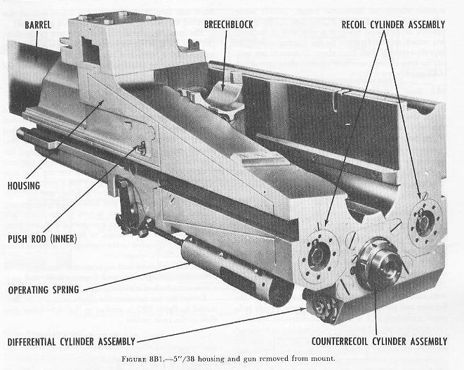
| B. Five-Inch 38-Caliber Assemblies 8B1. General The 5ö/38 caliber gun is a semiautomatic, dual-purpose, pedestal- or base-ring-mounted gun which uses semifixed ammunition. The principal features of 5ö/38 caliber gun assemblies arc as follows: 1. Vertical sliding-wedge breech mechanism. 2. Hydraulic recoil and hydropneumatic counter-recoil systems. 3. Power-operated rammer. 4. Power-operated elevating and training gear. 5. Movable-prism telescopes. 6. Power-operated fuze-setting projectile hoist (except on mounts of type 4 listed in article 8B27). 7. Power-operated powder hoist on all twin mounts and some singles. The operating principle of the 5ö/38 caliber gun is the same for all of the installations found on naval vessels. Minor variations in mechanical features reflect either improvement in design or the special requirements of certain installations. The majority of these variations are in mount design. The gun, slide, and housing assemblies, the breech mechanism, and their associated parts are almost identical in all mounts. The greatest variation in these parts occurs in the twin mount, in which the gun emplacements form left and right gun assemblies, alike in all respects except for the reversed left and right arrangements of the two gun, slide, and housing assemblies, the breech mechanism, and their component parts. Each assembly is mounted separately in carriages on a large rectangular platform. This difference changes the appearance of the gun assembly but does not affect the mechanical operating principles. Twin mount assemblies are installed on battleships, cruisers, carriers, and destroyers. Single mounts are found on carriers and destroyer escorts and on many of the older cruisers and destroyers, as well as on various types of mine-craft, landing craft, patrol craft, and auxiliaries. The main purpose of this section is to describe the basic features, the function, and the mechanical operation of the 5ö/38 caliber twin mount assembly. In as much as the two gun assemblies are identical in operating principles, only the right assembly will be discussed, unless otherwise stated. Other types of 5ö/38 mounts are discussed briefly at the end of the section. 8B2. Ammunition The gun uses semifixed ammunition consisting of a 54-pound projectile and a case assembly weighing about 28 pounds, which includes a 15-pound powder charge. The projectiles used are antiaircraft common, common, illuminating, and WP smoke. The ballistic performance obtained with a 15-pound service charge is as follows: initial velocity, 2,600 feet per second; maximum horizontal range, 18,000 yards; maximum vertical range, 37,300 feet. The gun is capable of sustained firing at a rate well in excess of any which can be attained by the loading crew. An experienced crew can load about 15 rounds per minute for long periods, and may attain a short-period rate of 22 rounds per minute. 8B3. Gun The gun is a radially expanded monobloc barrel which weighs about 2 tons. The rifling has a uniform twist of 1 turn in 30 calibers. The bore is chromium-plated from the forward portion of the powder chamber to the muzzle. The barrel is connected to the housing by means of a bayonet-type joint and locked by a key and key-bolt seated in a keyway in the barrel. This design facilitates regunning the mount without dismantling the breech mechanism or other parts. 8B4. Housing The housing is a rectangular block-shaped forging about 5 feet long and less than 2 feet wide between its parallel side faces. Its forward portion is machined to receive the barrel. In the center is a vertical well accommodating the breechblock; and to the rear of this, aligned with the barrel bore, is a trough-like ammunition-loading tray. Three bores in the after end of the housing and parallel to the gun bore axis provide twin recoil cylinders and a single counterrecoil cylinder. Each side face of the housing has a fore-and-aft slot forming the bearing surface for the slide guide rails. The housing assembly supports the gun in the slide, prevents the gun from rotating, and moves on the slide guides during recoil and counterrecoil. Other housing attachments and their operations are discussed later in this section. |
 |
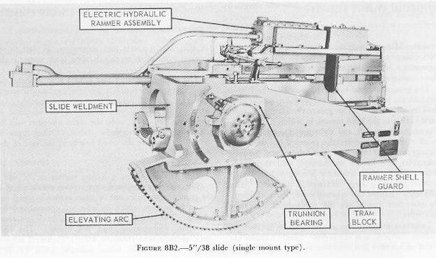 |
| 8B5. Slide The slide, shown in figure 8B2 is a large box-shaped structure within which the housing moves in recoil and countercoil. It is open at the top and bottom, and closed at the rear by a removable plate. The rear plate forms a seat for the support-bar housing of the countercoil mechanism. The top center of the rear plate provides a mounting surface for the case tray and guide plate. The front plate has a circular opening for the gun, a gun support bearing, and openings for the piston rods. The gun housing is supported and guided by two guide rails bolted to the inner side plates. The elevating arc, gun-port shield, and rammer mechanism are secured to the slide. The slide assembly is supported in the carriage by integral trunnions on roller bearings. The slide encloses and supports the housing and its assemblies during recoil and counterrecoil, and provides a method of elevating and depressing the gun. Except for the rammer, the single mount slide illustrated in figure 8B2 is similar to the right-hand gun slide in the twin mount. TEXT PAGE 160 |
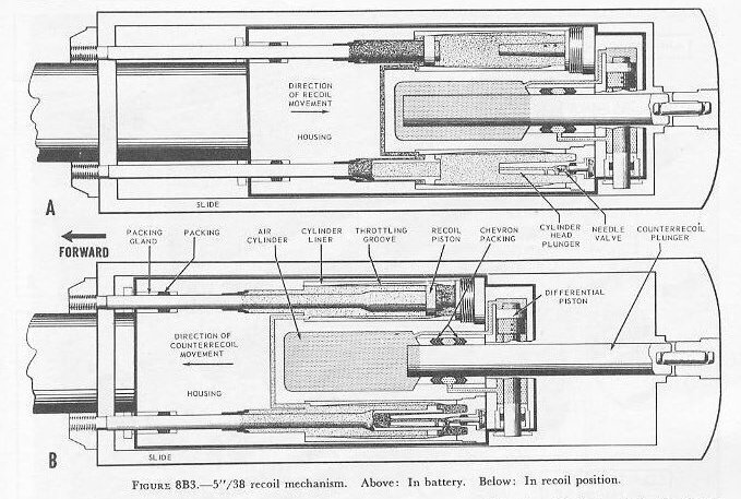 |
| 8B6. Recoil system The recoil system (fig. 8B3) utilizes pistons working in twin hydraulic cylinders to absorb the major shock of recoil, and to provide a buffer for counterrecoil, cushioning its return to battery. The piston rods, which are integral with their pistons, extend forward from the hydraulic cylinders through the housing (through a series of bronze sleeves and packing glands), and are secured to the gun slide by piston rod yokes and nuts. Therefore, the pistons and rods remain stationary in recoil and counterrecoil while the cylinders move. The after ends of the pistons are open and hollow to admit the buffer plungers. The twin recoil cylinders are formed by two longitudinal bores in the housing parallel to the gun axis. Into these bores are fitted bronze sleeves or liners about 18 inches long, having in their inner surfaces three equally spaced grooves of variable depth. As explained in chapter 5, these grooves control and throttle the amount of hydraulic fluid passing from one side of the piston to the other, and so insure the proper rate of recoil brake action. Pressure in both cylinders is kept equal by a pressure equalizing line. The cylinder heads closing the after end of the cylinder serve as combination cylinder heads, buffer plungers, and seats for adjusting valves. As the gun is returned to battery in counterrecoil, the buffer plungers enter the open pistons and produce a dashpot effect. Escape of fluid through each plunger during this action is controlled by a needle valve (adjusting valve) which alters the size of the opening in the plunger through which the fluid is passing. Thus the valves control the rate at which the gun returns to battery at the end of counterrecoil, and the smoothness with which its forward motion stops. These valves are usually set before the gun is installed on a ship. |
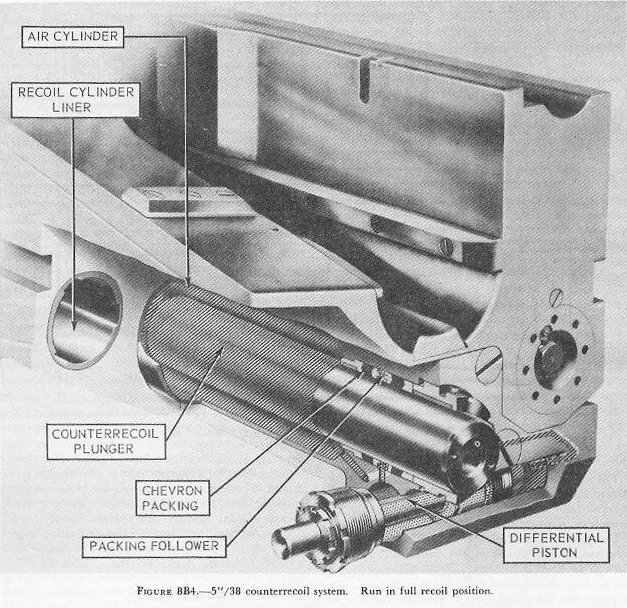 |
| 8B7. Counterrecoil system The counterrecoil system is a hydropneumatic type of recuperator. The cylinder is formed by a bore in the after part of the housing, below the loading tray and parallel to the gun axis. The counterrecoil plunger, a highly polished, hollow cylinder about 2 feet long and 3 1/2 inches in diameter, extends out of the after end of the air cylinder through a chevron packing and packing gland. It is coupled to the rear plate of the slide by the support block, support bar, and support bar housing. See figure 8B4. This coupling arrangement is not rigid, but is designed to permit enough freedom of motion so that the counter-recoil plunger can align itself with the packing gland, thus preventing distortion of the packing and consequent air leakage through the packing gland. When the gun is in battery, normal pressure in the air cylinder is kept at 1,450-1,550 psi. Recoil compresses the air further and the pressure rises to approximately 2,250 psi. Fluid under pressure is forced to the chevron packing from the differential cylinder through drillings in the air cylinder forging. See figure 8B4. As the barrel and housing move aft in recoil, the recoil pistons and piston rods are held stationary by the slide while the recoil cylinders move with the housing. Recoil fluid is forced past the pistons through the variable depth grooves, and the movement of the recoiling parts is retarded and finally stopped. Assisting this brake action of the recoil system is the action of the recuperator. As the air cylinder moves aft over the stationary counterrecoil plunger, the air pressure in the cylinder is increased. When the rearward action of the recoiling parts has been stopped, the highly compressed air within the recuperator main cylinder drives the cylinder and gun housing forward. The first 6 inches of this counterrecoil motion is retarded only by the recoil fluid as it is displaced past the recoil piston. Then the plungers of the recoil cylinder heads enter the open ends of the recoil pistons and produce their dashpot effect (as explained in chapter 5), as controlled by the needle valves. When the gun is not in use, the housing is secured to the slide by a metal safety link. (It should always be disconnected before firing, but neither gun nor mount will be damaged if this is not done.) |
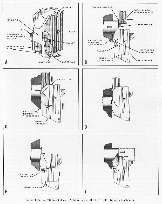 |
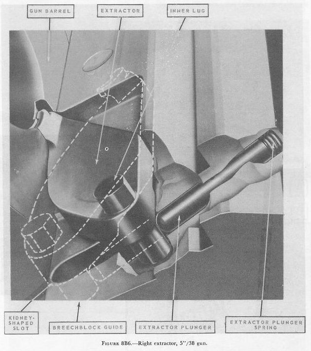
| 8B8. Breechblock The breechblock (fig. 8B5) is a vertical sliding wedge which fits into a rectangular well cut through the center of the housing from top to bottom. Ribs on the left and right sides of the block match grooves in the breechblock guides of the housing and guide the block as it moves up and down to close or open the breech. They also function to transmit the recoil shock from the breechblock to the housing. The upper portion of the forward face of the block is beveled, and the breechblock guides slant forward slightly from bottom to top. The result is twofold. As the block rises it also moves slightly forward to wedge the cartridge case home, while the beveled forward face assists the wedging action. A bore penetrating the block from rear to face contains the firing mechanism. Additional bores house the sear, sear safety latch, retracting lever bearing blocks, and operating shaft central arm. Slots or grooves machined in the right and left sides of the block serve as camways for the extractor inner lugs. These slots are fitted at the upper end with pallets---shoulders against which the inner Jugs bear when the block has been dropped. 8B9. Extractors Extraction of the empty cartridge case is a mechanical operation accomplished by the extractors as the breechblock is lowered during counterrecoil. The two extractors are rocker arms, each with inner and outer lugs projecting from the opposing flat surfaces at its base. The outer lugs ride in kidney-shaped slots in the breechblock guides of the housing. In these slots the lugs can move in a fore-and-aft direction, but not up and down. The extractors also have eccentric inner lugs which fit into slots machined in each side of the breechblock. As the block drops, these inner lugs ride in their slots and are forced forward by the curved portion. Since the extractors are rocker arms rocking on the breech-face, the upper portion of each extractor is forced aft when the inner lugs are forced forward. The lips on the extractors engage the rim of the cartridge case. The quick forward motion of the lower end of the extractors causes an accelerated flip of the extractor lips to the rear, thus extracting the case (fig. 8B5.). Spring-loaded extractor plungers (fig. 8B6) push forward against the outer lugs and assist in extraction. |
 |
| The breechblocks held down against the action of the operating spring by the inner lugs bearing on the pallets. (See fig. 8B5.) When the block is in its lowest position, the extractor inner lugs are in the curved portion of their slots and are held there by the extractor plungers, which are pushing forward on the outer lugs. The lower surfaces of the lugs and the upper surfaces of the pallets are flattened to provide good bearing surfaces. The breech cannot be closed as long as the lugs bear on the pallets. However, when the gun is loaded, the rim of the case strikes the extractor lips and forces them forward. (See fig. 8B5.) The extractor rocker action moves the inner lugs aft against the action of the extractor plunger springs, until they clear the pallets and are in the vertical portion of the slots. The operating spring can then force the breechblock upward to close the breech. 8B10. Operating shaft The vertical motion of the breechblock is controlled by the operating shaft (fig. 8B7), which rotates in bearing caps on the bottom of the housing. The operating shaft is rotated automatically by cam action during the firing cycle, or manually by movement of the hand-operating lever. The operating shaft has cranks on both ends. A lug extends out from the operating-shaft crank at the left end to engage the operating-shaft cam plate for semiautomatic operation of the breech mechanism. The crank at the right end (hand-operating crank) has a projecting lug which engages a crank of the hand-operating mechanism for manual operation. Near the left end of the shaft is a curved, cam-like arm to which the operating-spring chain is attached. In the center is the operating-shaft central arm, made up of two parallel arms, with a pin passing through both arms. The pin also passes through the curved slot of the retracting lever which operates between the arms during shaft rotation. The ends of the pin project beyond the sides of the central arm and carry the bearing blocks. These bearing blocks slide in the inclined bearing-block ways (fig. 8B5) within the bottom of the breechblock. Thus rotation of the shaft causes vertical movement of the breechblock. |
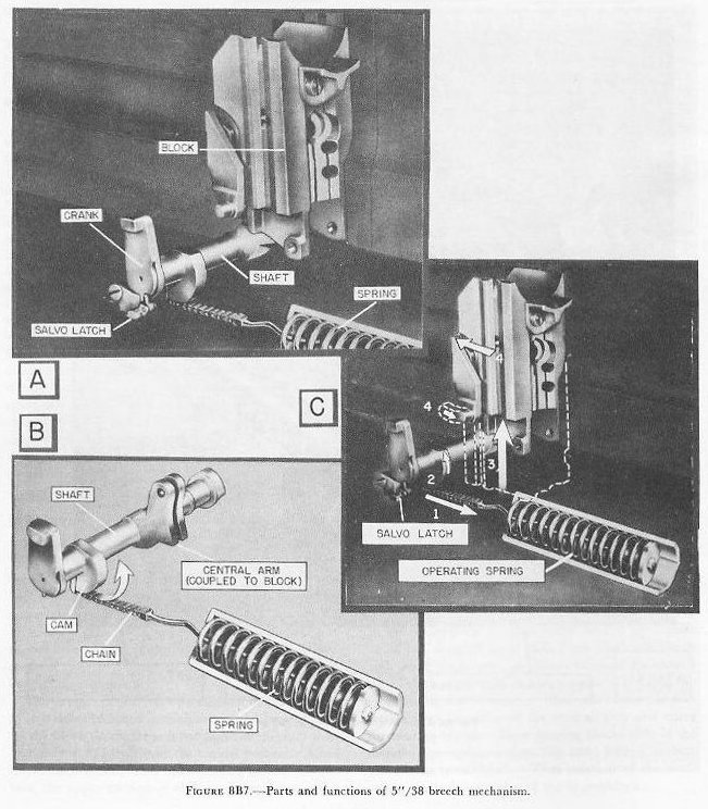 |
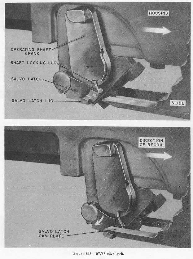
| 8B11. Salvo latch The salvo latch, shown in figure 8B8, is a positive-type latch, mounted on the left operating-shaft bearing. With the breechblock raised and the gun in battery, the latch is engaged with the latching lug on the operating-shaft crank. Engaged, it prevents the opening of the breech of an unfired gun by preventing rotation of the operating shaft unless the latch is tripped by hand. During gun recoil movement, the latch-operating lug projecting from the salvo latch passes beneath the salvo-latch cam plate. This forces the salvo latch down, permitting the spring-loaded pawl to snap forward and retain the latch in its disengaged position by bearing against the lower surface of the latching lug. The operating-shaft crank is now free to rotate to permit opening of the breech. When the breechblock is closed again, rotation of the operating shaft causes the latching lug to rotate aft and force the salvo-latch pawl aft. This permits the salvo latch to rise under spring pressure and engage the latch lug, so that the breech is locked. |
 |
| 8B12. Operating-spring assembly This assembly consists of an operating chain, connecting rod, coil spring, adjusting nut, and cylindrical housing for the spring. One end of the operating chain is attached to the operating shaft (fig. 8B7), while the other end is secured to the connecting rod. This rod passes through the coil spring and is attached to the after end of it by the adjusting nut. The housing which encloses the spring is bolted to the lower part of the gun housing (fig. 8B7). Opening the breech compresses the spring, because the rotation of the operating shaft winds up the chain connection on the shaft, pulling on the adjusting nut on the other end of the spring. In this way the spring stores up the energy for closing the breech. The adjusting nut provides a means for varying the spring tension, which in turn regulates the force of the breech closing. |
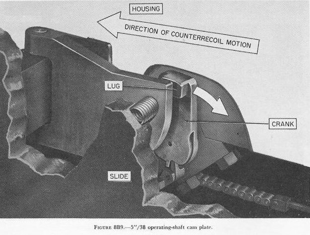 |
| 8B13. Cam plate A pivoted cam plate, mounted in the inner left face of the slide, as shown in figure 8B9, controls the rotation of the operating shaft by means of a crank arm at the left end of the shaft. During recoil, the crank pushes the cam plate outward toward the slide about the pivot pin. This movement compresses a spring placed between the cam plate and the slide. The operating shaft does not rotate at this time. At the instant the crank moves abaft the cam plate, the spring snaps the cam plate back into position. During counterrecoil, the lug on the operating-shaft crank strikes the curved portion of the cam plate and is forced downward by it. This motion of the crank rotates the operating shaft and lowers the breechblock. The central inboard section of the cam plate tapers down to a wedge-shaped groove which is opposite the position of the lug on the crank when the gun is in battery and the breechblock is open. This groove permits the crank to rise as the breechblock closes. A movable cam-plate retractor, has a cam surface which positions the cam plate against the slide so that the cam plate will be inoperative. The breechblock must then be lowered by a handcrank. The cam-plate retractor can be moved forward to the position designated by symbol S (single) for manual operation or pulled rearward to the position designated by symbol A (automatic) for semi-automatic operation, in which the cam plate will open the breech during counter-recoil. |
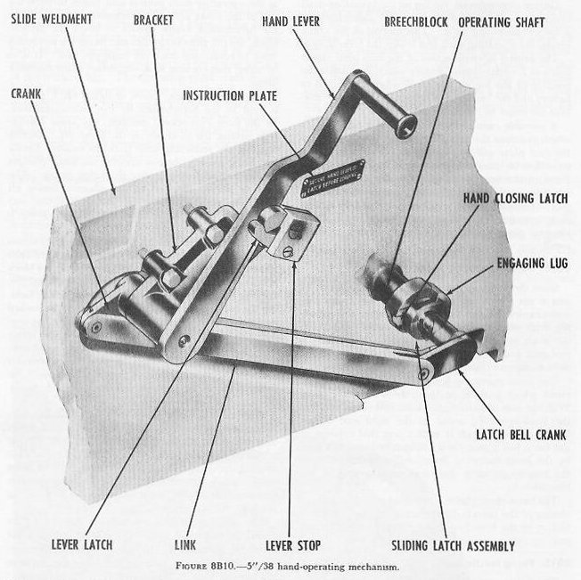 |
| 8B14. Hand operating lever Since the hand operating lever on the 5ö/38 caliber gun is not a recoiling part, it is necessary to provide a mechanical linkage which acts to engage the operating shaft when the gun is in battery and still permits the shaft to move freely in recoil. The linkage is mounted and pivoted on the right outside face of the slide, as shown in figure 8B10. The hand operating lever is linked to a latch bell crank which projects in from the side of the slide. With the gun in battery, the latch bell crank contacts the hand-operating crank at the right end of the breech-operating shaft in such a way that rotation of the latch bell crank (in a counterclockwise direction by the hand-operating lever) will cause rotation of the breech-operating shaft and the lowering of the breechblock. The hand-closing latch is provided to permit manual closing of the breech during action in case there is a failure in the breech-operating spring or connecting rod. |
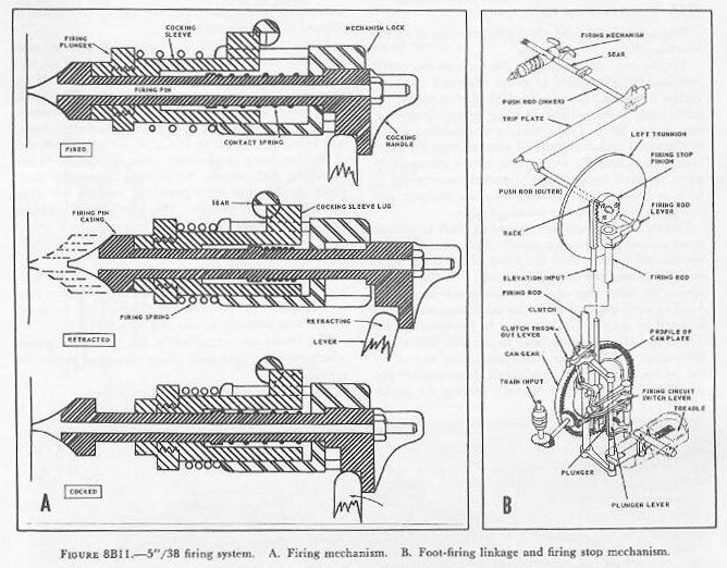 |
| 8B15. Firing mechanism The firing mechanism provides for percussion and electrical firing. Electrical firing requires that the firing pin be insulated from the gun, but be in contact with the primer when the breechblock is closed. Percussion firing with the pin resting on the primer is obtained by striking the pin with a plunger. The arrangement of the firing mechanism in the cocked position is shown in figure 8B11, part A. The retracting lever is pivoted in the breechblock extensions. The vertical arm of the retracting lever engages a flange on the firing-pin unit. A pin carried in the operating-shaft central arm passes through the slot in the lower arm of the retracting lever. When the breechblock crank rotates to lower the breech-block, the pin rides in the slot and forces the retracting lever to rotate and cock the firing-pin unit. It is to be noted that cocking is accomplished when the block drops. The firing-pin unit, shown in figure 8B11, part A, is held in the breechblock by the mechanism lock. In the fired (uncocked) position, the firing plunger rests against the shoulder on the firing pin. During cocking, the retracting lever pulls the cocking handle and firing pin aft, thereby drawing the firing plunger to the rear and compressing the firing spring. The cocking sleeve, attached to the plunger, moves aft until the cocking-sleeve lug just passes the sear shoulder. At the same time, the contact spring is compressed. As the breechblock closes, the retracting lever allows the contact spring to move the firing pin forward until it gently but firmly contacts the primer after the block is fully closed. During the movement of the firing pin, the sear shoulder engages the cocking-sleeve lug, holding the cocking sleeve and firing plunger in the cocked position. As the breechblock finishes closing, the central arm of the operating shaft raises the sear safety latch, disengaging its lug from the groove in the sear. The pin is then in position to pass the current for electrical firing, and ready to transmit the blow of the firing plunger for percussion firing (part A of fig. 8B11). Percussion firing is initiated by the pointer, who presses a foot treadle. Through a system of linkages and push rods (discussed in the next article), the sear is pushed inward against its spring. This releases the cocking-sleeve lug through the sear notch. The firing spring drives the cocking sleeve and firing plunger forward, and the blow of the plunger drives the firing pin into the primer, thus firing the gun. The gun cannot be fired until the breech is fully closed, because until then, (1) the firing pin does not touch the primer, (2) the sear is locked by the sear safety latch, and (3) the sear is out of alignment with the inner push rod of the foot firing linkage. 8B16. Foot-firing linkage and firing stop mechanism The foot-firing mechanisms of both guns are operated by a foot treadle mounted on the outboard side of the left carriage. They are controlled by the pointerĺs right foot when it is desired to fire the guns by percussion. As the pointer depresses the treadle, its action is transmitted through a system of cranks and levers to the outer push rod located in the slide. See part B of figure 8B11. Movement of this push rod pivots the trip plate inward. This moves the inner push rod (in the housing) inward. The end of this rod is in contact with the sear when the breech is fully closed. Movement of the inner push rod displaces the sear, and the gun fires. To ensure that the firing rod can be rotated only when the gun is not pointed into own ship, a firing stop mechanism is used. The principles of this mechanism were explained in chapter 5, and the mechanism as it is installed on 5-inch mounts is shown in figure 8B11, part B. It functions to interrupt fire both by percussion and electrically, whenever the axis of the bore is aligned with some part of the shipĺs structure. A spring-loaded plunger that bears against a circular cam plate permits fire when it is in contact with a recessed part of the cam plate surface, and stops fire when in contact with a raised part of the cam plate surface. The pattern to which the cam is cut is plotted individually for each gun mount. As the gun is elevated, the plunger is positioned vertically by the elevation input rod and rack. As the mount is trained, the profile cam is rotated by the bevel gears and pinion to correspond with the position of the mount. Thus the position at which the plunger strikes the profile cam will be determined by the elevation and train of the gun. If the plunger rides on a portion of the cam which is not recessed, the clutch throw-out lever and clutch lever do not contact each other. The pointer pressing the treadle does not move the firing rod, and he cannot fire the gun If, on the other hand, the plunger rides on a recessed portion of the profile cam, the bell crank will move the linkage so that the clutch throw-out lever and clutch lever are in contact, and motion of the pointerĺs foot on the treadle will be transmitted to the firing rod, and thus the gun will be fired. The profile cam must be so cut that when it is positioned by an angle of elevation and train of the gun which would damage own ship, the plunger will strike a non-recessed surface of the cam. The movement of the plunger is also transmitted to a switch in the electric firing circuit when the plunger rides out of the recessed surface of the profile cam. 8B17. Gas ejector system Gas ejectors function to prevent the entry of powder gases into gun mounts, to safeguard against the danger of flarebacks, and to assist in maintaining a rapid rate of fire by clearing the bore of gases. Air under pressure of approximately 75 psi is piped to the gun mount from the shipĺs supply. It moves through tubing and air passages bored in the gun housing to nozzles located in the breechblock guideways and pointed toward the gun bore. During counterrecoil of the gun, a gas ejector valve, located in the forward and top of the housing is cammed open and the gas ejection action begins. The valve is tripped and closed by action of the rammer operating shaft as the next round is rammed. A hand lever permits manual opening and closing of the valve. 8B18. Gun operating cycle When the gun is fired, the following cycle of operation takes place. The force of the expanding gases causes the barrel and housing assemblies to move rearward in recoil within the slide. During the first part of recoil, the salvo latch is disengaged and the operating shaft is then free to rotate. The braking or retarding action of the recoil and counterrecoil systems stops the rearward action, and the recuperator moves the recoiling parts forward again. This forward movement, in turn, is checked and smoothed by the dashpot and buffing action within the recoil cylinder. During counterrecoil the operating shaft is rotated upon contact with its cam plate. This rotation drops the breechblock, retracts the firing pin, sets the sear, and compresses the operating spring. As the breech opens, the outer lugs of the extractors are thrust forward by their plungers while the inner lugs are moved forward by their slotted camways in the breechblock. The lips of the extractors snap to the rear, extracting the empty case, and the inner lugs come to rest on the pallets, holding the breechblock down against the pressure of the operating spring. During the initial movement in counterrecoil, the gas ejector valve is tripped to open position. When the next round is rammed, the cartridge case trips the extractors, rocking the inner lugs off the pallets. The gas-ejector valve is tripped to CLOSE by rotation of the rammer-operating shaft. The block rises, wedging the cartridge case, moving the retracting lever to permit the firing pin to contact the primer, and bringing the sear in line with the inner push rod of the foot firing mechanism. Simultaneously, as the operating shaft rotates, the latching lug on the shaft picks up the salvo-latch pawl and enables the salvo latch to lock the breech. The gun is now ready to fire the next round. |
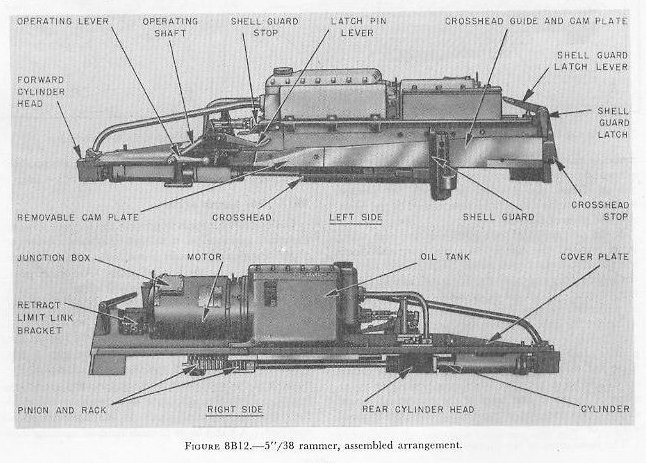 |
| 8B19. Rammer mechanism The rammer assembly is a semiautomatic, electric-hydraulic unit mounted at one side of the loading tray on the upper rear portion of the slide. It is designed to function properly at any gun elevation. The power unit consists of a 7 1/2-hp electric motor which drives a hydraulic pump mounted in the oil supply tank. The rammer itself (fig. 8B12) includes: 1. a hydraulic cylinder 2. a piston and piston rod 3. a pinion secured to the after end of the piston rod by a yoke 4. a fixed rack (fig. 8B13) secured to the inner face of the slide 5. a crosshead, consisting of a crosshead detail (movable rack), a crosshead arm, and a shell guard or spade 6. control valves and operating levers In open mounts the rack-and-pinion arrangement (No. 5) is omitted. The crosshead drives the spade direct. |
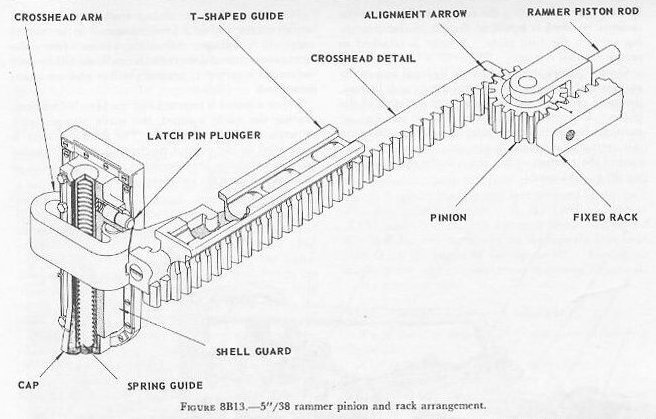 |
| The hydraulic pump introduces oil under pressure into the cylinder to drive the piston forward for ramming and aft for retracting. This motion is transmitted to the crosshead through the pinion which is meshed with both the fixed pack and the crosshead detail (movable rack). The rammer piston pulls the pinion forward about 26 1/2 inches, forcing it to rotate between the two racks so that the crosshead is translated a distance equal to twice the linear travel of the pinion. This pinion arrangement permits the use of a shorter cylinder which can be completely enclosed within the shield. The spade rams the projectile and case into the chamber at the same time. The face of the spade is padded with rubber and backed with canvas to prevent damage to the base of the case during the ramming operation. The spade is mounted on the crosshead in such a manner that it can be moved upward about 5 inches against the action of a vertical spring placed between spade and crosshead. A spring-loaded plunger (plunger latch) projects from the inboard side of the spade. The crosshead guide and cam plate is mounted along one side of the loading tray. Its purpose is to guide and support the crosshead, and to provide cam surfaces upon which the plunger latch rides and hence controls the vertical motion of the spade. After a round is rammed, the breechblock rises and forces the spade upward about 3 inches. After the gun is fired, as the spade and crosshead move aft in retraction, the plunger latch rides up an inclined cam surface on the cam plate and the spade is raised an additional 2 inches. The upward movement of the spade, totaling about 5 inches, is sufficient to permit the ejected case to pass under the spade. A projection on the forward left side of the cross-head engages with a rammer interlock mechanism at the end of the ram stroke, latching the crosshead to the housing. The interlock mechanism is a spring-loaded catch partly enclosed in the safety-link bracket. The crosshead is unlatched by relative motion between housing and slide during the first part of recoil as the rammer interlock is forced to the left by the unlatching cam on the cam plate. A lever is attached to permit manual release. |
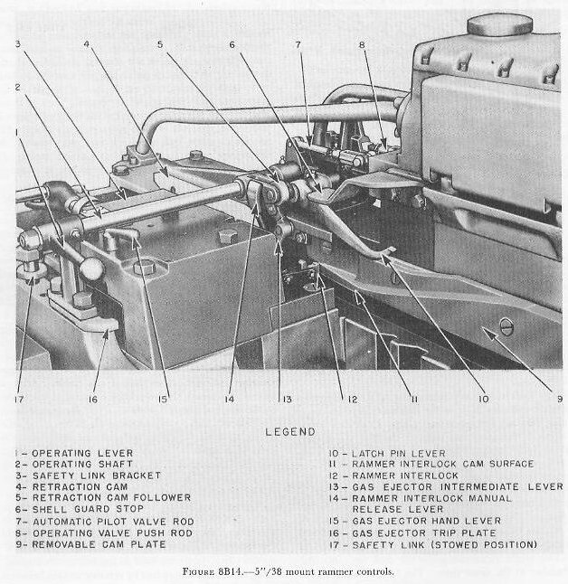 |
| Control valves, operated partly by hand and partly automatically through a control shaft and linkage, mounted as in figure 8B14, control the motion of the piston. Movement of the control shaft and linkage positions hydraulic valves which cause the piston to ram, retract, or remain at neutral. An operator can control the rammer at any point in the cycle by moving the control lever. Near the end of the retract stroke, the crosshead engages a retract-control rod connected to the control valves by a linkage. When the rammer forces the retract-control rod a short distance aft, the linkage and valves are returned to neutral position and retraction is stopped. When a round is rammed and the breechblock rises, forcing the spade upward, the spade plunger latch actuates the latch-pin lever. The latch-pin lever is connected to the control mechanism so that upward movement of the lever positions the control valve to neutral, releasing the ram pressure. Automatic retraction of the rammer is accomplished by means of a cam follower attached to the control shaft which rides over the cam mounted on the upper part of the housing. The retraction cam moves rearward during recoil of the gun, operating the cam follower which rotates the control shaft to the retract position. 8B20. Ramming cycle Assume that the cartridge case and projectile have been placed in the loading tray and that the spade is behind the case in position for ramming. The projectile man throws the hand control lever into the RAM position; the spade moves forward, forcing the ammunition into the gun; and the crosshead is locked to the housing by the crosshead interlock latch. (Fig. 8B14.) When the rim of the cartridge case strikes the extractors, the breechblock rises and forces the spade upward. As the spade rises, the plunger latch forces the latch-pin lever upward. This action returns the control valve to the neutral position. After the gun is fired, the following actions take place during the first part of recoil: (1) The crosshead rides back with the recoiling gun and housing; (2) the crosshead unlatching cam pushes against the cross-head interlock, latch, releasing the crosshead; and (3) the rammer control shaft is positioned for retraction by the retraction cam, and the rammer continues to retract under its own power. During retraction, the plunger latch rides on the inclined cam surface on the cam plate, and the spade is raised to provide the necessary clearance for the ejected case. Near the end of the retract stroke, the crosshead engages the retract-control rod. When the rammer forces the retract-control rod a short distance aft, the control valves are returned to the neutral position and retraction is stopped. The spade is held in its upper position by a latch which must be released manually by means of the spade-release lever before the spade can drop into position to start another ramming cycle. There are two inclined cam surfaces on the forward part of the crosshead guide and cam plate which are not used in ordinary operation. The plunger latch is raised above these surfaces by the rising breechblock, and rides past them during recoil, directly to the cross-head guide and cam plate. The lower of the two cam surfaces is used when exercising the rammer with the breech mechanism idle and the breech open. Then the spade is not raised by the breechblock, but is raised by the latch riding the lower cam surface. The upper cam surface is included in the design as a precautionary measure. If the ram stroke is started with the spade in its up position, the spade plunger latch will ride the upper cam surface. This prevents damage, should the breechblock be closed. 8B21. Loading operation Assume that the gun crew has been firing. After the ejected case has cleared the loading tray, the gun captain depresses the spade release lever to drop the spade. The powder man takes a powder case out of the powder hoist, removes the primer-protecting cap, and places the case on the loading tray. The projectile man removes a projectile from the projectile hoist and places it on the loading tray just forward of the case. The projectile man then pulls the rammer lever to RAM, and the charge is rammed home. After the gun fires, the hot case is ejected through the case ejection chute for angles of fire up to 40 degrees. For higher angles of fire, the hot case must be removed manually by the hot-case man. |
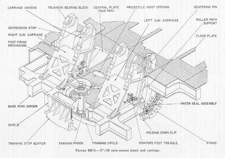 |
| 8B22. Carriage, stand, and roller path The general arrangement of these parts is shown in figure 8B15. The carriage is an assembly of the base-ring type. The right and left gun carriages are secured to the four fore-and-aft girders which are supported by the base ring. The base ring supports the twin guns, their elevating and training drives, hoists, sights, shield, and other parts of the rotating assembly. The upper roller path is fitted into the base ring. The stand is a large, circular steel casting with a flange at the bottom around the outer circumference for bolting to the gun foundation. It is designed to accommodate the training circle and lower roller path. The upper roller path furnishes a bearing surface for the horizontal rollers and the radial rollers. A radial bearing surface secured to the inner vertical surface of the stand serves as the other bearing surface of the radial bearings. The horizontal rollers bear on the lower path, permitting the mount to rotate. Bronze separators support and separate the rollers. Secured to the base ring are four holding-down clips, designed to fit under the training circle with a small amount of clearance. They serve to steady the mount during rotation and firing, and to hold the mount to the roller path. |
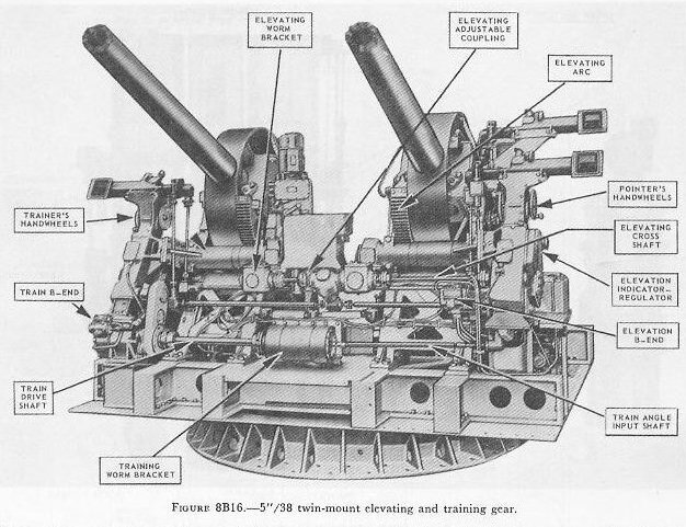 |
| 8B23. Training and elevating gear These assemblies, illustrated in figure 8B16, are electric-hydraulic power drives of similar type in arrangement, operation, and control, but different in size and capacity. The training gear is driven by a 40-horsepower motor and the elevating gear by a 10-horsepower motor. Each has its own hydraulic transmission unit. Each transmission unit consists of a hydraulic pump connected by pressure lines to a hydraulic motor. The output of the pump to the motor is controlled by an indicator-regulator or by a control unit. Through each transmission unit, the constant-speed, unidirectional input from the electric motor is converted into a reversible, variable-speed output to the respective elevating arcs or training rack. Further discussion of automatic control equipment is found in chapter 10. Both pointer and trainer have two shift levers available. One of these is a speed selector, which permits a selection of either high speed or low speed operation. The other lever provides a choice of 4 methods of gun movement control, 3 of which employ power drive while the fourth is a manual operation. The 4 methods of gun movement control are as follows: 1. Automatic. This is remote director control of the hydraulic pump by electrical signals transmitted to the indicator-regulators of the elevating or training assemblies. The speed selector lever must be in the HIGH SPEED position if automatic control is selected. 2. Local. In this mode, rotation of the pointerĺs or trainerĺs handwheel positions a servo device which in turn positions an A-end tilt box of the appropriate drive. This type of control, then, is similar to automatic, except that rotation of the handwheels takes the place of the electrical signals from the remote point. Either high or low speed may be selected. 3. Hand. This is power drive control using the handwheels with their shafts and gears to position the A-end tilt box without the intermediate use of the servo mechanism. Either high or low speed may be selected. 4. Manual. This is manual drive of the gun movement, with the handwheels geared directly to the training rack or elevating arc. The hydraulic transmission and the power drive are bypassed and hence inoperative. Normally, only low speed is employed in manual. The selector levers of the pointer and trainer operate independently, so that a different gun movement control or speed may be employed in train from the control or speed in use in elevation. |
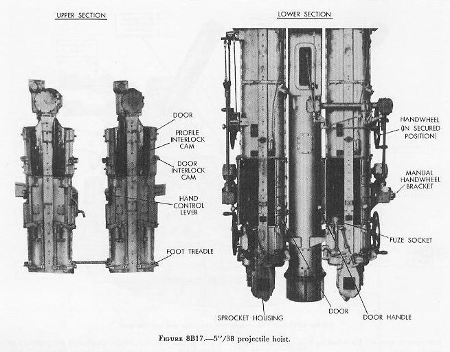 |
| 8B24. Projectile hoists The twin mount is equipped with right and left hoists of similar design. They are semi-automatic endless-chain, enclosed, dual-tube hoists with electric-hydraulic drive. An auxiliary manual drive is provided for emergency use. Figure 8B17 shows the upper end of the hoists in the gun mount and the lower end in the handling room. Each hoist is separately driven and controlled, but an indicator-regulator simultaneously adjusts fuze settings for both hoists through shafts and gears. The hoist drive consists of a 10-hp electric motor, a hydraulic pump enclosed in a tank, a motor unit, and a control unit. The hydraulic pump is connected to the hydraulic motor by pressure lines. |
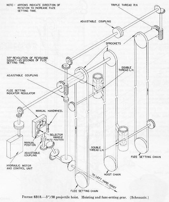 |
| The hydraulic motor is geared to a chain-driving sprocket in the upper end of the hoist. A lower idler sprocket is enclosed in the lower sprocket housing. An endless power chain or hoist chain is held between the two sprockets as shown in figure 8B18. On either side of the power chain are fuze-setting drive chains. These will be discussed later. Two projectile flights (fuze sockets) are attached to the power chain of each hoist. The flights are so placed that 1 is at the upper end of 1 tube when the other is at the lower end of the opposite tube. The upper and lower position of the flights are the limiting points of chain movement. |
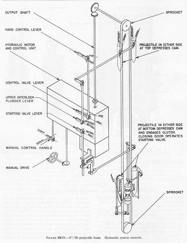 |
| The control gear shown in figure 8B19 consists of a system of linkages from the top and the bottom of the hoist to the hydraulic control unit. At the bottom of the hoist, a control cam protrudes into each hoisting tube. A projectile placed in one of these tubes depresses the cam and causes its clutch to engage the shaft to the starting lever. Then, when the hoist door is closed on that projectile, the shaft is turned, actuating the starting valve. At the top of the hoist, a projectile-interlock cam protrudes into each tube. If a projectile is at the top of the hoist, the cam will be depressed, positioning the interlock valve in neutral, so that the power drive cannot hoist. The doors at the top of the hoist are also equipped with interlock cams. When either door is open, its cam acts to prevent hoisting. The control cam and interlock cams thus provide safety features which will prevent the power drive from functioning: 1. When the projectile is being placed in the hoist. 2. When the loaded flight reaches the top position. 3. While the projectile is being removed from the hoist. Assume that a projectile is in its flight at the top of the hoist and that the other flight is empty and at the bottom of the hoist. With the projectile-interlock cam at the top depressed, the hydraulic unit is maintained in neutral. Now a projectile is manually loaded in the other tube and the lower door is closed. The depressed control cam and the closed door actuate the starting valve, but the interlock valve prevents a hoisting cycle. The projectile at the top is then manually removed. This removal of the projectile frees the interlock cam and forces the upper door open. As long as the door is open, the door interlock cam prevents hoisting. When the projectile clears the door, the door snaps closed under spring pressure, and the door interlock is released. The hydraulic motor drives, the projectile rises, and the empty flight goes down. As the projectile reaches the top of the hoist, the interlock cam is depressed, placing the hydraulic controls in neutral. The above cycle will continue as long as shells are loaded and removed. A handwheel, geared to the power-drive output shaft through a clutch, provides an auxiliary manual drive to be used in case of power failure. Projectiles are manually loaded and removed from the hoist. Manually operated upper and lower projectile-ejector mechanisms facilitate removal. This type of hoist furnishes the gun mount with a rapid, continuous supply of projectiles. The fuze-setting mechanism consists of (1) a fuze-setting indicator-regulator, (2) fuze-setter chains, and (3) projectile flights. These three components, shown schematically in figure 8B18, are called regulator, fuze chains, and flights in the following discussion. The regulator is a device which sets the fuze by controlling the position of the fuze chains. It is mounted at an angle on the carriage inboard of the right gun. The regulator can be set for either manual or automatic control by means of a selector lever. In manual control, the gun-crew fuze setter turns the manual handwheel to actuate the chain-setting drive, and the time setting is effected by one of the following methods: 1. By matching pointers, in which case the fuze setter matches pointers on 2 sets of regulator dials, one set of which is actuated by electrical signals from the computer in the director system, and the other set by rotation of the manual handwheel. 2. By setting the desired fuze time on the regulator dials, in which case the manual handwheel is turned until the dials indicate the fuze time opposite fixed index marks. This method is used when the computer is disconnected from the regulator. In automatic control, the manual handwheel is disengaged, and the fuze chains are automatically positioned by an electric power drive in the regulator. The power drive is controlled by electrical signals from the computer. The gun-crew fuze setter has no control over the regulator in automatic control. |
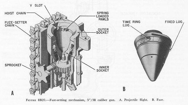 |
| A flight consists essentially of an outer socket attached to the hoist chain, and an inner socket so mounted on ball bearings that it can rotate within the outer socket. (Fig. 8B20, left.) The inner socket is geared to a sprocket which engages the fuze chain. The fuze chains are endless chains mounted on the outboard sides of the hoist chain. A fuze is set by rotating the time-ring lug (fig. 8B20, right). The projectile must be placed on the hoist with the fuze fixed lug in the V-slot to obtain correct settings. The initial fuze setting is SAFE, and during the fuze-setting operation the time ring is rotated from the maximum time setting down to the setting required. The pawls on the inner socket will engage the time-ring lug when these parts are in alignment. Further rotation of the socket, after engagement, sets the fuze. During hoisting, the point in the flight travel at which engagement does take place depends upon the fuze setting desired. The sprocket transmits fuze-setting adjustment from the fuze chain to the time fuze in the following ways: 1. By movement of the flight with respect to the fuze chain when the projectile is hoisted. The gearing is so arranged that movement of the flight from the lower to the upper position causes the inner socket to rotate almost exactly one revolution in a direction to reduce the time setting on the fuze. A rotation of 315░ is equivalent to 45 seconds fuze-setting time. 2. By movement of the fuze chain. This is controlled by the regulator. From the above discussion it is apparent that if a high fuze setting is desired, the regulator must so position the fuze chain that the pawls will engage the time-ring lug late in the hoisting cycle. The time ring will then be turned a small amount during the remainder of the flight travel and the setting will be high. On the other hand, the pawls are positioned for early engagement in making low fuze settings. Thus, in obtaining a given fuze setting, it is only necessary to make the setting on the regulator which positions the fuze chain, and then hoist the projectile. Changes in fuze setting may be introduced at any time while the projectile is in the hoist by changing the setting on the regulator. The fuze will be set for the time indicated by the regulator when the projectile is lifted out of the flight, even though it has remained at the delivery end of the hoist for some time. Projectiles without mechanical time fuzes, such as VT-fuzed or target projectiles, can be hoisted by this equipment. Such projectiles may even be hoisted interspaced with mechanical time fuze ammunition, if so desired, for, having no fuze lugs, the VT-fuzed or target projectiles are unaffected by the fuze-setting mechanism of the hoist. Such a situation occurs in AA firing when mechanical time fuzes are fired inter-spaced with VT fuzes to aid in spotting the burst onto the target. |
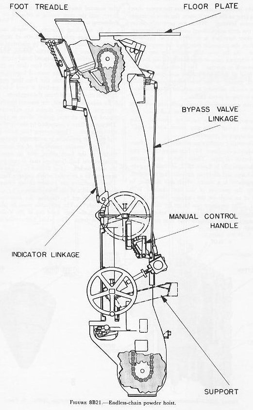 |
| 8B25. Powder hoist The twin mount is equipped with right and left hoists of similar design (fig. 8B21). They are semiautomatic endless-chain, enclosed, single-tube hoists with electric-hydraulic drive. A manual drive is provided for emergency use. Figure 8B21 shows the upper hoist location. Each hoist is driven and controlled by an electric-hydraulic drive. This drive consists of an electric motor, pump, and tank unit connected by piping to a hydraulic motor and control unit. The hydraulic motor is geared to a chain-driving sprocket in the upper end of the hoist. An idler sprocket is mounted in the lower end. A conveyor chain, provided with five flights uniformly spaced, is held between the sprockets. It is reversible, for hoisting or lowering powder cases. A HOIST-STOP-LOWER hand-operated control lever, connected to the hydraulic control unit, regulates the direction of motion. |
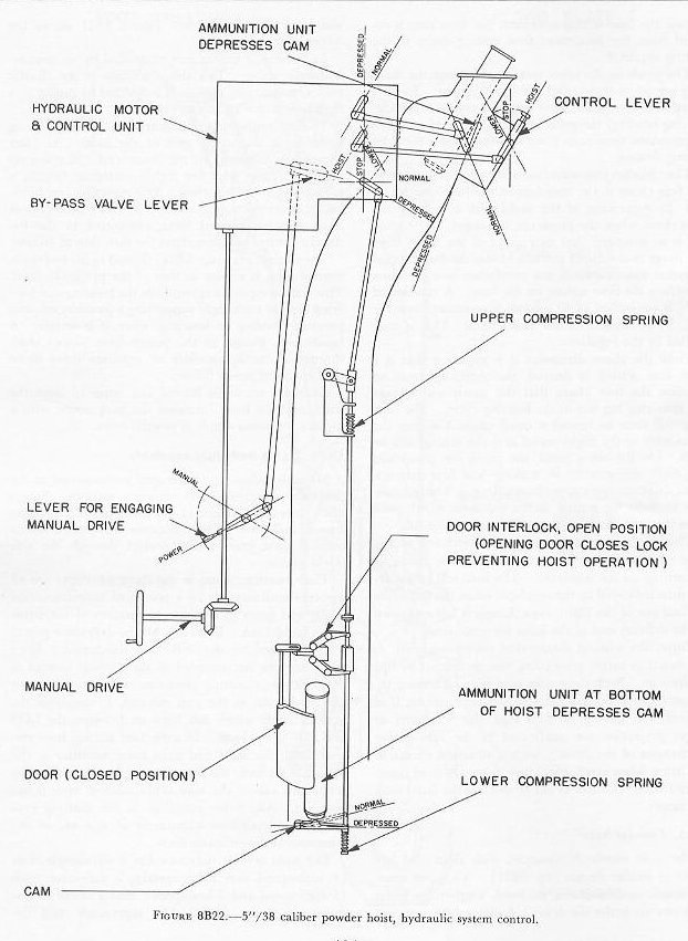 |
| The control gear (fig. 8B22), linked to the hydraulic control unit, is similar to that of the projectile hoist. This control equipment regulates the hoisting and lowering limit of each flight supporting a powder case, and prevents hoisting or lowering when it is unsafe. A handwheel, geared to the power-drive output shaft through a clutch, provides an auxiliary drive to be used in case of power failure. Cases are manually loaded and removed from the hoist, and the hoist furnishes the gun mount with a rapid, continuous supply of powder cases. |
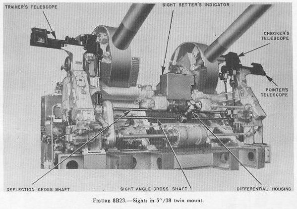 |
| 8B26. Sights and sight assembly Movable prism-type telescopes are mounted at the pointerĺs, checkerĺs, and trainerĺs stations. Figure 8B23 shows the location of the telescopes and the sight setterĺs indicator. The telescopes are located within hooded sight ports which project through the side shield plates. The elevating prisms in the three telescopes are all moved simultaneously by a system of interconnecting shafts and gears in response to rotation of the sight-angle handcrank. Similarly, all the deflection prisms are positioned by the deflection handcrank. Since the telescopes are mounted on the carriage instead of the slide, the elevating prisms must be rotated by the elevating gear, as the gun elevates, to maintain the vertical angle which has been set between the LOS and axis of the bore. In deflection setting, however, since both the sight and guns move together as the mount is trained, the lateral angle between the telescope and axis of the bore is maintained, once it has been set. Adjustable couplings in the shafting provide for independent adjustment of any one of the telescopes or the indicator dials. |
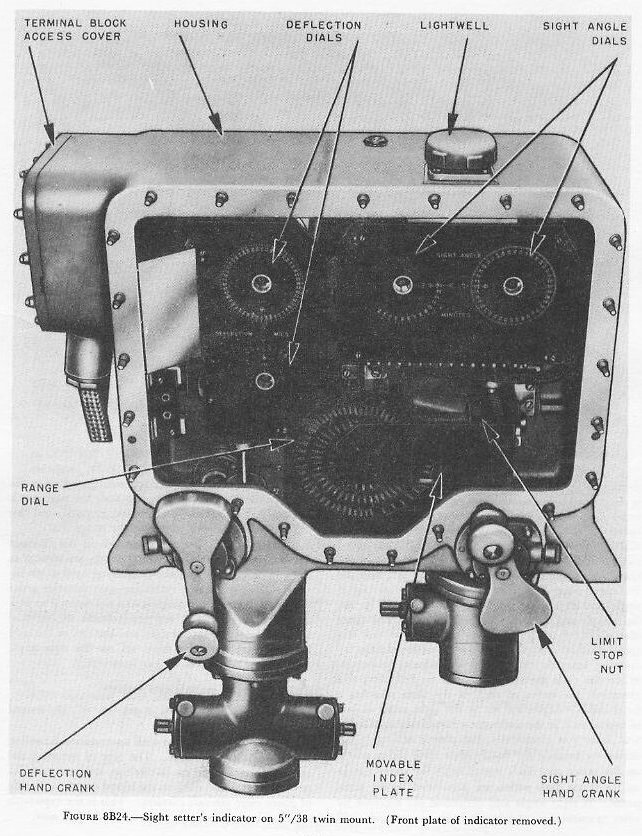 |
| The sight setterĺs indicator has 2 sight-angle dials (1 high-speed and 1 low-speed), 2 deflection dials (1 high-speed and 1 low-speed), and a range dial as shown in figure 8B24. The sight-angle and deflection dials consist of two dials each; an inner dial is electrically operated from the computer. The inner dials have a position index mark, but no graduated scale. The sight-angle high-speed outer-ring dial is graduated in minutes of arc, and the low-speed outer dial in 100 minutes of arc. The deflection high-speed outer-ring dial is graduated every mil, and the low-speed outer dial every 100 mils. The outer sight-angle and deflection ring dials are operated by the sight-angle and the deflection handcranks. The range dial is geared to the sight-angle handcrank and has spiral graduations every 100 yards, with readings increasing inwards radially in a clockwise direction. When the dials are at zero position in deflection and elevation, the index of each of the dials matches a fixed index. Sights are set by the sight setter in one of two ways. If the computer is furnishing sight angle and deflection electrically, the proper setting is obtained by turning the handwheels until index marks on the outer ring dials match with the index marks on the inner dials which are positioned by the computer. If sight angle and deflection are received by voice transmission, the handwheels are turned until the ring dials show the desired settings opposite the fixed pointers. In the latter method, the sight-angle settings desired might be expressed in yards, and this setting would then be made on the range dial. Since the telescopes are mounted on the carriage instead of the slide, the elevating prisms are rotated as the gun elevates as well as by changing sight-angle inputs. The two variable quantities, gun elevation order and sight angle, are combined in a differential to produce this effect. The net result keeps the vertical angle between the line of sight and the axis of the bore in agreement with the angle set on the sight-angle dials for any position of the gun in elevation. 8B27. Types of mounts and shields There are four main types of 5ö/38 mount assemblies: 1. Enclosed twin mount with ammunition-handling room beneath the mount. The type of mount is the standard installation on battleships, cruisers, and destroyers. It is also used on the island (starboard) side of Essex class aircraft carriers. This is the type with which this chapter has been concerned up to now. 2. Enclosed single mount with ammunition-handling room beneath the mount. The enclosed single mount is the old standard destroyer-type mount. It is now found on the many minecraft and auxiliaries which have been developed from the older classes of destroyers, as well as on most of the destroyer escorts in the Fleet and many large auxiliaries (repair ships, destroyer tenders, etc.). 3. Open single mount with ammunition-handling room beneath the mount. This mount was specially developed for installation in the walkways on the port side of aircraft carriers. It is also occasionally found on auxiliary vessels. 4. Open single mount without ammunition-handling room. Mounts of this type can be installed on ships without extensive reconstruction. For that reason it is a type of installation frequently used on converted vessels originally of merchant types. There are no ammunition hoists associated with this mount. 8B28. Other characteristics of 5ö/38 caliber twin mounts All twin mounts are enclosed in a shield of armor plate which varies in thickness from 1/4 inch on destroyers to 21/2 inches on battleships. The shield is a boxlike structure about 15 1/2 feet long, 15 feet wide, and 10 1/2 feet high. It provides weather, blast, and splinter protection for the crew. There are doors on both right and left sides near the after end, through which the operating personnel enter or leave the gun room. Other doors and access cover plates are provided to make the operating mechanisms more accessible for inspection and repair. Two identical openings in the front plates provide gun ports. The case-ejector chutes lead to doors in the rear plate of the shield. A roof hatch is located near the after end of the gun mount. Where mount location renders it necessary, this hatch is equipped with a blast hood or shield. Sight hoods mounted on the side shield plates provide protective covering for the three telescopes. The hoods are fitted with hinged shutters and handcranks, so that they can be opened and closed from the inside. A ventilation system installed in the gun room supplies air to various parts of the mount and handling room. All twin mounts are equipped with various types of electrical power installations. All power motors have associated controllers and push-button arrangements to start and stop them. The power equipment also includes electric heaters for warming the gun room and the hydraulic equipment. Illumination in the gun and handling room is supplied by the shipĺs general illumination circuit. This circuit also includes outlets for (1) battle lanterns, (2) window-wiper motors attached to each telescope, and (3) the battle illumination transformer. The battle illumination system provides illumination by small lamps at all instruments, and controls, such as telescopes, dials, each gun breech, and the bottoms of the projectile hoists. The mount is provided with two sources of electricity for firing the guns: (1) a motor-generator (shipĺs power supply), and (2) a 6-volt battery located in the mount handling room. A selector switch mounted near the pointerĺs station controls the source. The firing circuit provides for electrical firing either locally or from a remote station. Gun-elevation, gun-train, fuze-setting, and sight-setting electrical signals are supplied to the indicator-regulators and the sight setterĺs indicator in the mount by fire control circuits from the computer. The communications facilities for the twin mount include (1) a voice tube between gun room and upper handling room, (2) an automatic telephone which is part of the shipĺs general communications system, (3) a battle telephone systemĺ (sound-powered telephone circuits) between mount and fire control stations, (4) an auxiliary sound-powered telephone circuit with call bell between the mount and the lower ammunition-handling room, and (5) a powerful loud-speaker which is connected to the director and plotting room. Approximately 27 men are required to man all stations in the mount and the upper handling room. Additional personnel in the lower handling room and magazines are required when fire is to be sustained for considerable periods. 8B29. 5ö/38 caliber single mounts Aside from the number of guns installed, there are four significant differences between the various 5ö/38 caliber single mount assemblies and the 5ö/38 caliber twin mount assembly. These differences are in (1) the rammer, (2) the sight mechanism, (3) the power drive, and (4) the ammunition-handling arrangements. The rammer on the 5ö/38 caliber single mount is not equipped with the 2 to 1 gear ratio arrangement described in article 8B19. The rammer piston travels the same distance in its cylinder that the crosshead and spade move during the ramming stroke. Although final results are the same, sights on single mounts are different in design from those on the twins. There is no differential for adding gun elevation and sight angle. Instead, the linkages to the sight prisms on enclosed single mounts are driven by a large sight driving gear inside the large circular housing next to the slide. This gear in turn is driven by a banjo-shaped assembly which moves in elevation with the slide. In the banjo are a worm and worm gear mechanically connected to the sight angle crank. Turning the crank causes this gear train to rotate a pinion meshed with the sight driving gear, which in turn positions the sight prisms. Sights on single open mounts are in general similar to those on single enclosed mounts, except on open mounts not equipped with movable-prism telescopes. On such mounts, the mechanical linkage briefly described above positions the pads on which the sight telescopes are mounted. Several different types of power drive are used with single mounts, depending upon the type of mount and the ship upon which installed. On ships which are equipped with fire control installations the drives are such as to provide for automatic control, local control, and manual control. On many converted merchant ships only local and manual controls are available. The 5ö/38 caliber single mounts of the handling-room type are equipped with projectile hoists of the same type as used in twin mounts. There are, however, no powder hoists. Powder is passed from the upper handling room to the gun room through a scuttle. Mounts of other than the handling-room type are not equipped with hoists, but do have a fuze setter located outboard of the projectile manĺs station. |