| GENE SLOVER'S US NAVY FIRE CONTROL PAGES NAVAL ORDNANCE AND GUNNERY, VOLUME 2 CHAPTER 28 ANTISUBMARINE WARFARE |
| HOME INDEX Chapter 28 Antisubmarine warfare A. General B. QHBa scanning sonar equipment C. Controling the attack D. OKA-1 Sonar resolving equipment E. Depth-determining sonar equipment |
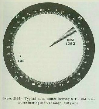
| B. QHBa Scanning Sonar Equipment 28B1. QHBa scanning sonar equipment-general At the present time, sonar equipment model QHBa is in use on some of the operational destroyers, and at most training activities. Although this will be the only equipment described in this text, it is now being replaced in the Fleet by model SQS4 and related equipment. This model differs from the QHBa in details of construction and circuitry, but not in general principles. Model QHBa combines echo-ranging and listening equipment in one unit. On a cathode-ray tube (CRT)-scope, similar to a radar PPI-scope, it provides a continuous visual display of echo reception from all directions in azimuth, and an audible response from any desired single direction. The QHBa equipment consists of the following five major units: 1. Indicator control. 2. Transmitter-receiver. 3. Transducer. 4. Scanning switch assembly. 5. Data converter. These units, their functions, and their operation will be discussed in detail in the articles following. 28B2. QHBa indicator control The QHBa indicator control, as its name implies, controls the operation of the QHBa equipment and provides for the video and audio presentation of target echoes. 1. Video presentation. At the instant that a pulse of sound energy is projected into the water in all directions, a luminous spot on the CRT scope (i. e., the trace of the electron beam) begins to spiral outward from the center. This spiraling motion is in reality a combination of two motions. One, a straight-line movement of the spot toward the periphery of the scope, is called the linear sweep. The other, a circular movement of the spot about the center of the scope, is known as the circular sweep. The linear sweep occurs at a relatively slow rate of speed. The circular sweep, on the other hand, occurs at a relatively high angular rate (1750 rpm). The result is that the QHBa operator observes the motion of the electron beam trace or spot not as a spiral but rather as an expanding circle of constantly increasing radius. When the outgoing pulse of sound energy strikes a submerged object such as a submarine, part of its energy is reflected as a target echo. This echo, after being received, changed into an electrical signal, amplified, and rectified, is applied to the control grid of the cathode-ray tube and causes a bright spot or pip on the CRT-scope. Because of the persistence of the scope, this pip, along with other target pips, remains on the scope long enough to be reinforced by another returning echo. The result is a map-like presentation which is invaluable in target detection. The range and bearing of a sonar contact can be determined easily from the position of the pip displayed on the CRT-scope. The distance from the center of the CRT to the edge of the screen represents a definite range. (For example, during search this distance represents 3750 yards.) The beam trace moves outward from the center at a uniform speed, and takes exactly twice as long to reach the edge of the screen as the sound pulse takes to travel the corresponding distance. When the sweep reaches the position to represent any given range, the sound pulse will have had time to reach a target at that range and return. Thus the distance of a target pip from the center of the screen provides an accurate measure of target range. And, since the scope presentation is so oriented that true North is at the top of the screen with own ship at the center, the angular displacement of the pip from the top of the screen indicates the true sonar bearing Bq of the target. See figure 28B1. |
 |
 |
 |
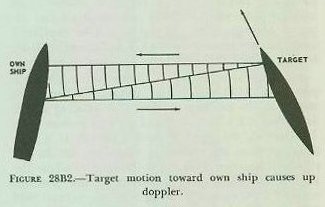
| On the CRT-scope, a dotted line indicates the true direction of the stern of the ship (i. e., ship’s head plus 180°). Thus the operator can, at any time, determine the relative bearing of the target as well as the direction of the ship’s baffles. The dotted line extends in the direction of the ship’s stern, rather than its bow, so as not to obscure the target pip during an attack. 2. Audio presentation. The audio scan covers eleven degrees of bearing. It is controlled by the bearing knob, which is discussed in a subsequent paragraph. The direction of the audio scan (1. e., the direction in which the QHBa equipment is trained to receive an echo) is indicated on the CRT scope of the QHBa indicator control by a bright line called a cursor. The cursor flashes on the scope at the instant the outgoing sound pulse is transmitted. Its length is adjustable. When the cursor bisects the target pip, and its length is so adjusted that its outer end just touches the pip, the cursor bearing will be the true sonar bearing Bq, and the cursor length will furnish an indication of sonar range Rq. The returning echo, after conversion to an electrical signal and amplification, is changed to an audible frequency and sent to a loudspeaker near the QHBa indicator control, where it is heard as a sharp “ping.” This ping is of value in target identification, and in the determination of doppler. Up doppler results from an increase in frequency, or pitch, of the returning sound waves, caused by a target’s true motion toward own ship. Down doppler results from a decrease in frequency of the returning sound waves, caused by a target’s true motion away from own ship. A target that causes up doppler is said to have bow aspect, while a target that causes down doppler has a stern aspect. In other words, target motion or aspect (but not range rate) can be deduced from the doppler effect. To determine doppler, the sonarman must compare the pitch of two echoes; the first echo, consisting of reverberations from the water immediately surrounding the transducer, is compared with the echo that returns from the submarine. The relative frequency of the target echo depends on whether the submarine compresses the sound wave (up doppler, indicating bow aspect), expands it (down doppler, indicating stern aspect), or sends it back unchanged (no doppler, indicating beam aspect). See figure 28B2. Own ship’s motion affects the pitch of the initial echo; but since it has the same effect on the pitch of the returning target echo, the doppler detected by comparison of the two is not changed by own ship’s motion, and it is this comparison that indicates the target aspect. To facilitate the detection of doppler, doppler nullifier circuits are installed in the QHBa. These circuits remove the effect of own ship’s motion on the pitch of the echoes heard by the sonarman. In this way the variations caused by changes in own-ship speed and course are eliminated, making doppler detection easier. |
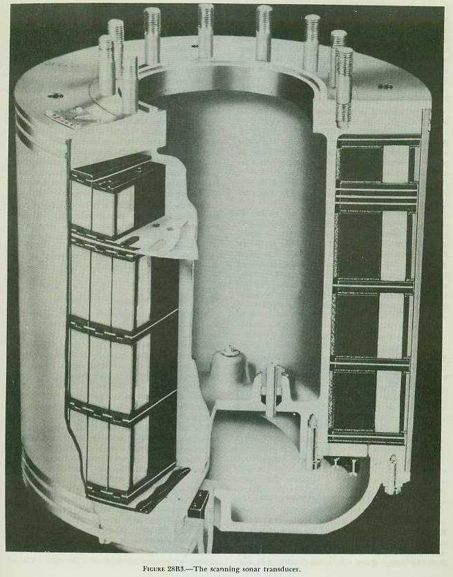
| 3. Controls. Figure 28A2 shows the various knobs, switches, etc., on the control panel of the QHBa indicator control. Collectively, they are used to operate all the scanning sonar equipment. a. Bearing knob and bearing dial. The true bearing of the cursor (and hence of the audio scan) is controlled by the bearing knob and is indicated on the bearing dial. The knob, when turned, will change the cursor bearing at a relatively slow rate. However, if the knob is pressed in and rotated one-eighth of a revolution in either direction, the cursor will slew rapidly. As explained previously, if the cursor is positioned so that it bisects a target pip, the cursor’s bearing will be the true sonar bearing Bq of that particular target. Bq can be read on the bearing dial. b. Range knob and range dial. It was noted above that the length of the cursor (and hence cursor range) could be varied. The range knob is the control which determines this length. It is located directly above the bearing knob and has adjacent to it a range dial on which approximate values of cursor range can be read. Again, if the outer tip of the cursor just touches a target pip, the value of range indicated on the range dial will be an approximate value of sonar range Rq to that particular target. Such a value, of course, is of interest only when making an initial contact re port. Accurate values of Rq, as will be explained later, are determined by the OKA-1 range recorder for use in the antisubmarine fire control problem. c. Keying selector switch. This switch has three positions: 1500, 3750, and LISTEN. When it is moved to the position marked 3750 (during search and when tracking a target at a range greater than 1500 yards), the scale of the CRT-scope (i. e., the distance from the center of the scope to the periphery) becomes 3750 yards. Similarly, when the keying selector switch is moved to the position marked 1500 (when tracking a target within 1500 yards), the scale of the scope becomes 1500 yards. In each of these cases, the video sweep (i. e., the expanding circle) moves all the way out to the periphery of the CRT-scope before collapsing and starting anew from the center. Thus it can be seen that the keying selector switch controls not only the range scale of the CRT-scope but also the time between successive sweeps. Finally, when the keying selector switch is set on LISTEN, automatic sound-pulse transmission is stopped, underwater signaling by means of a hand key is possible, and the direction of ultra-sonic-frequency noise sources can be determined by observing the bearing of radial patterns on the CRT-scope which represent acoustic signals from those sources. In this position the expanding circular sweep is still sweeping across the face of the scope at a keying interval corresponding to 3,750 yards, although no sound beam is being transmitted. Any noise of sufficient volume and appropriate frequency is picked up by the transducer and displayed on the CRT-scope as a pie-shaped brightened area. The bearing of the noise source can be determined by positioning the cursor through the middle of the brightened sector. The range can not be determined, since the scope is saturated with noise. d. Cursor push button and cursor time switch. These controls determine the duration of cursor illumination. The cursor push button is pressed whenever it is desired to have the cursor remain lighted on the CRT-scope (in order to determine accurately the bearing of a target, for example). The cursor time switch is used to control the duration of the cursor “flash”; if moved to the SHORT position (the normal position during search), the cursor will appear only momentarily when the video sweep begins to move out from the center of the CRT-scope; if the switch is moved to the LONG position (the normal position during attack), the cursor will remain on during the scan period until shortly before the echo is expected to appear (until the video sweep is 200-300 yards short of the pip position). e. Other controls and indicators. The GAIN control adjusts the gain of both the video reception (the pip) and the audio reception (the ping) simultaneously. The AUDIO switch enables the operator to improve the signal-to-noise ratio (and hence the sharpness of the pip) whenever a noisy target is encountered. The MCC switch (an ON-OFF switch) is used for maintenance of close contact; that is, when moved to the ON position it causes the sound beam to be broadened vertically to permit tracking of targets at closer ranges. The MCC pilot light becomes lighted whenever the MCC-switch is on. The GYRO OFF pilot light, when illuminated, indicates that the top of the CRT-scope represents own ship’s bow rather than true North, because of a gyro failure. The mark signal switch and the aided tracking switch, located on the left and right sides of the control panel, respectively, are used in conjunction with the attack director and therefore will not be described here. 28B3. QHBa transmitter-receiver At the instant the video sweep begins to move outward from the center of the CRT-scope, the keying circuits of the QHBa indicator control send a signal known as the keying pulse to the QHBa transmitter-receiver. The pulse initiates operation of the transmitting circuits in the latter unit. The transmitting circuits, in turn, produce a high-voltage pulse of electrical energy at a proper supersonic frequency (about 25.5 kc) and transmit this pulse via the scanning-switch assembly to the transducer. Returning echo signals from the transducer, on the other hand, after passing through the scanning switch assembly, come to the receiver circuits of the QHBa transmitter-receiver, where they are amplified to a suitable level for audio and video presentation. The video signals, moreover, are rectified in order that they may be applied directly to the control grid of the CRT-scope in the QHBa indicator control for screen brightening. And the frequency of the audio signal is changed to a sonic or audible frequency, so that it may be heard over the loudspeaker used in conjunction with the QHBa indicator control. 28B4. QHBa transducer This unit is mounted in a sound dome below the hull of the ship. Its functions, briefly, are- 1. To convert the pulse of electrical energy received from the transmitter-receiver into a pulse of acoustic energy of the same frequency, and to project this pulse into the surrounding water in all directions in azimuth. 2. To receive the returning echoes and to convert them into electrical energy of the same frequency. These functions, it can be seen, are similar to those performed by the antenna of a radar. The transducer proper, shown in figure 28B3, consists of 48 staves mounted around the periphery of a circle in much the same manner as the staves of a barrel. The staves, in turn, are separated from the surrounding water by a rubber jacket. The density of this jacket is the same as that of sea water; thus any vibration of the staves is transmitted unaltered into the surrounding water. |
 |
 |
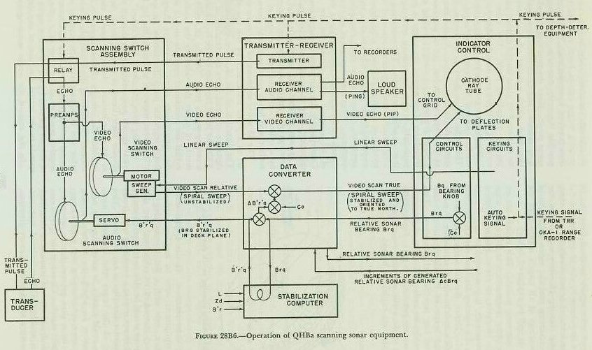 |
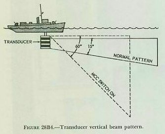
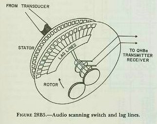
| Each stave consists of four elements. The lower three are of the same size, and are used with their counterparts in the other staves to form the nor-mat sound beam. The upper element is shorter than the other three. It is used with its corresponding elements in the other staves to form a beam which is broadened vertically and which, consequently, is desirable for the maintenance of close contact. The upper elements are used when the MCC (maintenance of close contact) switch is on. See figure 28B4. All the staves are made of a nickel alloy which has the property of vibrating whenever an alternating magnetic flux penetrates it. This property is known as magnetostriction. Each element of a stave is surrounded by a coil. During transmission, this coil receives an alternating current from the QHBa transmitter-receiver. When this current passes through the coil, an alternating magnetic field is produced which penetrates the element of the stave, causing it to vibrate and hence produce a sound wave. The magnetic field is so adjusted that the frequency of this vibration is the same as the frequency of the applied current. Once the sound pulse has been transmitted, the transducer staves act as microphones; and, upon receipt of a returning echo, the sequence of the events outlined above is reversed. The acoustic echo causes the staves to vibrate; and the vibrating staves, in turn, cause electrical currents to flow through the coils and hence to the transmitter-receiver. 28B5. QHBa scanning-switch assembly The QHBa scanning-switch assembly determines the bearings of returning echoes and hence of sonar contacts. It is installed electrically between the QHBa transmitter-receiver and the QHBa transducer, and therefore controls both the outgoing sound pulse and the returning echo. There are two scanning switches in this assembly, the video scanning switch and the audio scanning switch, each of which operates independently of the other. Essentially both are the same, mechanically and electrically. |
| 1. Video scanning switch. The video scanning switch consists basically of two metalized glass discs separated by a narrow air space. One disc is called the stator; the other, the rotor. The rotor and stator have 48 aluminum capacitor segments each, equally spaced about their peripheries. Each of the 48 segments of the stator is connected electrically to a corresponding stave of the transducer. On the rotor, 30 of the 48 segments are shorted out so that, in effect, there are only 18 active segments (i. e., 18 segments that can receive electrical signals from the stator). The stator of the video scanning switch is fixed. The rotor, however, is rotated at a constant rate of 1750 rpm. Consequently, target echo signals received from the 48 staves of the transducer by the 48 segments of the stator can be scanned consecutively, 18 at a time, by the rapidly rotating 18 active segments of the rotor. The scanning provides video indication of the sonar bearings of all targets within 360° arc in azimuth (as will be explained below). 2. Audio scanning switch. This switch has essentially the same construction as the video scanning switch. However, its rotor, instead of being rotated continuously, is positioned in any desired direction .by the bearing knob of the QHBa indicator control. Hence the 18 active segments of this rotor will scan echo signals from only 18 stator segments (and hence 18 transducer staves) when positioned in any one desired direction. This scanning provides an audio indication of the sonar bearing of any one particular target. Figure 28B5 is a diagram of the audio scanning switch and the lag lines (which are explained below). 3. Bearing determination. If the QHBa scanning sonar equipment were to employ a plane transducer (i. e., one with a flat transmitting/receiving surface) instead of its cylindrical one, this plane transducer would be able to transmit a sound pulse in (and hence receive a returning echo from) only one particular direction at any one time. The sonar bearing of the target echo in such a case, consequently, could readily be ascertained by noting the direction in which the transducer was trained. However, echo-ranging with such a transducer would be a slow process, hardly adequate for effective 360° search. Therefore the QHBa employs the cylindrical type of transducer described earlier in this article. This cylindrical type not only can transmit a sound pulse in every direction in azimuth simultaneously, but it can receive returning target echoes from any direction at any time between transmissions. This naturally makes possible the early detection of all targets within sonar range. Since the receiving transducer surface is cylindrical, and hence nondirectional, the direction from which a target echo is received cannot be measured by some simple method such as training the transducer itself. The video and audio scanning switches are used for this purpose. Whenever a sound wave strikes a submerged submarine, part of its energy is reflected as an echo. This echo, upon leaving the target, fans out in several directions at once. By the time it arrives at the transducer it has, for all practical purposes, a plane front (i. e., a straight leading edge). The transducer stave nearest the target in bearing consequently receives an acoustic echo signal sooner than its adjacent staves. The video and audio scanning switch stator segments connected to this stave receive, as a result, electrical echo signals (suitably amplified by the preamplifiers of the scanning-switch assembly) sooner than their respective adjacent segments. Thus the reception of all electrical echo signals by the stators is comparable to the reception of all acoustic echo signals by the transducer. Consequently, for purposes of target bearing determination, only the stators need be considered. It was pointed out previously that the sonar RECEIVER bearings of a target could not be measured readily by a cylindrical transducer because of its curved surface and hence nondirectional characteristics. The 18 active segments of the rotor are made to act as a plane transducer by the use of lag lines. The direction of the 18 active segments when the signal is received gives the bearing of the target. A similar set of lag lines can be found on the audio scanning-switch rotor. As the 18 active rotor segments of either the video or the audio scanning switch are positioned opposite any 18 segments of the appropriate stator, electrical charges on the stator segments jump the narrow air space to the active rotor segments and enter the lag lines. The lag lines effectively “slow down” these electrical signals proportionally so that all the signals, despite their times of receipt, leave the lag lines at the same instant. In other words, the lag lines combine the voltages of these signals in the proper manner (by shifting them into phase with one another and by appropriate attenuation) to produce a total voltage which will be a maximum when the angular position of the rotor (i. e., the midpoint of the arc formed by the 18 active segments) corresponds to the actual direction of the target. In the case of the audio scanning switch, this total voltage is sent to the receiver audio channel in the QHBa transmitter-receiver, where it is used to produce the audible “ping.” In the case of the video scanning switch, the total voltage is delivered to the receiver video channel in the QHBa transmitter-receiver, where it is amplified and rectified for use in the QHBa indicator control as a brightening signal. Since the circular sweep of the CRT scope in the QHBa indicator control is synchronized with and hence rotates at the same speed (1750 rpm) as the video scanning switch rotor, this brightening will occur at the correct bearing on the CRT-scope. 28B6. QHBa data converter This unit has two functions. For one thing, it orients the visual presentation on the CRT-scope of the QHBa indicator control so that the top of the scope represents true North rather than own ship’s bow. Thus, for any target, true sonar bearing (Bq) rather than relative sonar bearing (Brq) is indicated on the scope. The QHBa data converter performs its second function in conjunction with the stabilization computer. Together these two units stabilize (1) the visual CRT-scope presentation (by stabilizing the circular sweep), and (2) the audible loudspeaker reception (by stabilizing the training signal to the audio scanning-switch rotor). The result is that, as the ship rolls and pitches, the target pip on the CRT-scope will not shift its position, and the target ping from the loudspeaker will not be diminished in intensity because of the deck inclination. These corrections correspond to deck-tilt corrections in the gunnery system. 28B7. Keying circuit The keying circuit controls the transmission of the sound pulse. This keying circuit may be controlled automatically by the QHBa indicator control (with the keying selector switch), or remotely by either the OKA-l range recorder or the tactical range recorder. Whenever this circuit initiates a pulse, it accomplishes several functions almost simultaneously. These are- 1. It sends a pulse to the transmitting circuits of the transmitter-receiver which, in turn, send a high-voltage pulse of electrical energy via the scanning-switch assembly to the transducer. 2. It sends a signal to the scanning-switch assembly to operate a relay, which cuts out the receiving circuits of the transmitter-receiver during the time the outgoing pulse is being transmitted. 3. It collapses the previous video sweep from the CRT-scope and starts a new one by sending a linear sweep voltage to the sweep (synchro) generator of the video scanning switch; in the sweep generator this voltage is combined electrically with rotor rotation (1750 rpm) and returned to the CRT deflection plates as a new video (spiral) sweep. 4. It causes the cursor to flash on the CRT-scope. 5. It sends a signal to the depth recorder which starts the stylus excursion across the chart paper. 28B8. Summary Figure 28B6 illustrates, in simplified schematic form, the operation of the various units of the QHBa scanning sonar equipment. |