
INDEX Back to Main Fire Control Page
A. Fire Control Problem Chapter 26B
B. Basic elements of lead-computing sightsC. Gun sight Mark 15 Chapter 26C (This page)
D. Gun Fire Control System Mark 63 Chapter 26D
E. Gun Fire Control System Mark 56 Chapter 26E
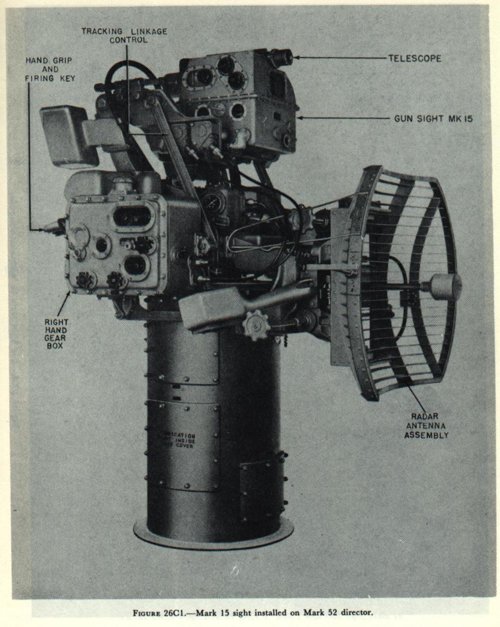
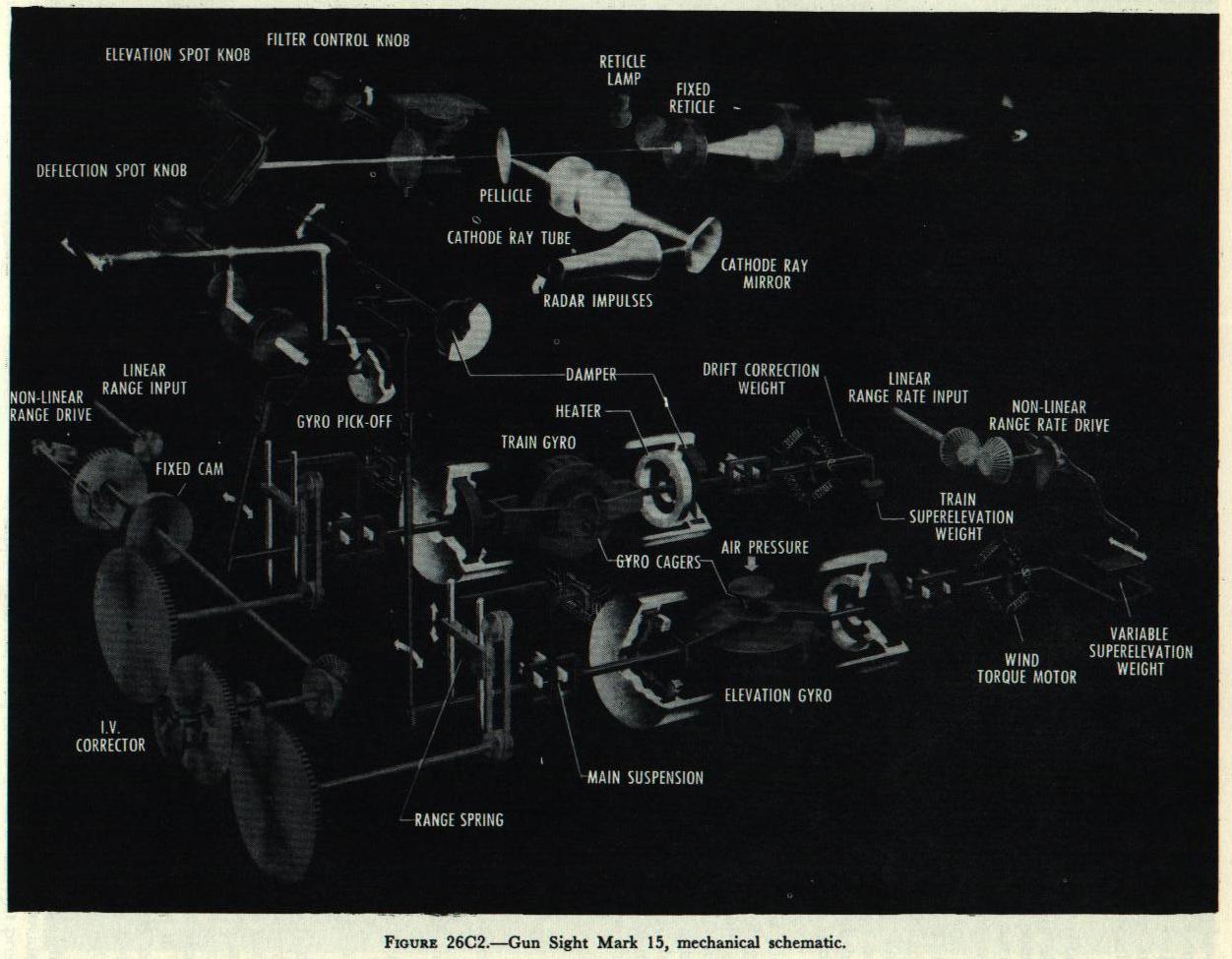 Figure 26C2 shows a mechanical schematic representation of the Mark 15 sight. The entire mechanism shown in this figure is enclosed in a case, which is shown in figure 26C1. In addition to the mechanism contained in the sight case, several other items of equipment are required. These items include:
1. A supporting platform which provides the freedom of movement in train and elevation necessary for tracking targets.
2. A unit to supply compressed air to drive the gyros.
3. A unit to solve the geometry of wind ballistic corrections.
4. A mechanical means of introducing range and range rate values.
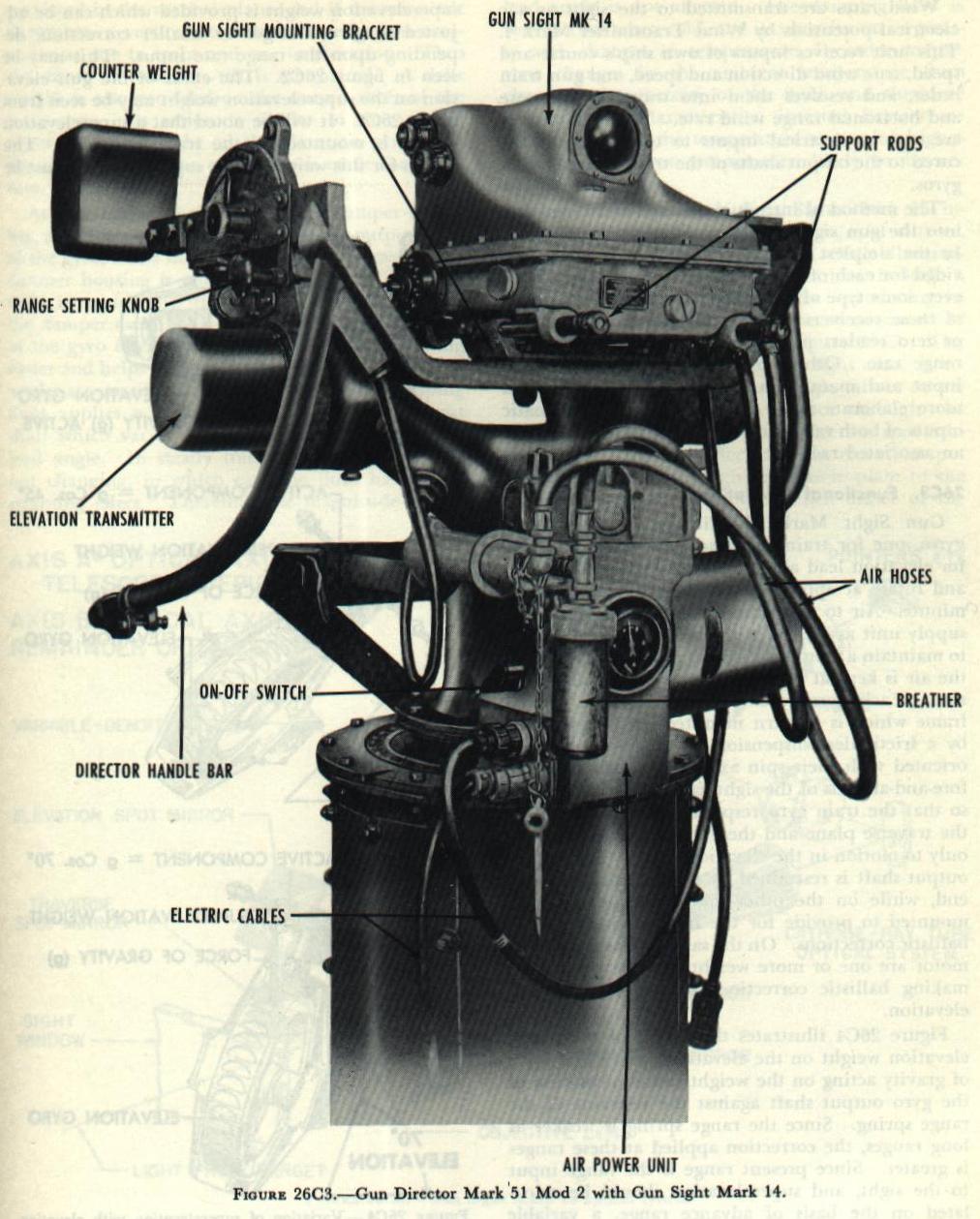 The Mark 15 sight may be mounted on any of several types of supporting platforms. For use as a simple fire control system it is mounted on a Gun Director Mark 51. Such a director is shown in figure 26C3, equipped with a short-range lead-computing sight, the Mark 14, which is somewhat simpler than the Mark 15. For use as a part of a more elaborate system, the sight may be installed on a Mark 52 director, as shown in figure 26C1, or on a Mark 1 director pedestal, as shown schematically in figure 26D1. class="w60pct padding" src="../PAGE_333_FIGURE_26D1.JPG" >
An air supply unit is furnished with each sight and installed near the sight. This unit provides a supply of dried, compressed air at a constant pressure to the sight for spinning the rate-of-turn gyros. Wind rates are transmitted to the sight as a-c electrical potentials by Wind Transmitter Mark 4. This unit receives inputs of own ship痴 course and speed, true wind direction and speed, and gun train order, and resolves them into traverse wind rate and horizontal range wind rate. These wind rates are sent as electrical inputs to torque motors secured to the output shafts of the train and elevation gyros.
The Mark 15 sight may be mounted on any of several types of supporting platforms. For use as a simple fire control system it is mounted on a Gun Director Mark 51. Such a director is shown in figure 26C3, equipped with a short-range lead-computing sight, the Mark 14, which is somewhat simpler than the Mark 15. For use as a part of a more elaborate system, the sight may be installed on a Mark 52 director, as shown in figure 26C1, or on a Mark 1 director pedestal, as shown schematically in figure 26D1. class="w60pct padding" src="../PAGE_333_FIGURE_26D1.JPG" >
An air supply unit is furnished with each sight and installed near the sight. This unit provides a supply of dried, compressed air at a constant pressure to the sight for spinning the rate-of-turn gyros. Wind rates are transmitted to the sight as a-c electrical potentials by Wind Transmitter Mark 4. This unit receives inputs of own ship痴 course and speed, true wind direction and speed, and gun train order, and resolves them into traverse wind rate and horizontal range wind rate. These wind rates are sent as electrical inputs to torque motors secured to the output shafts of the train and elevation gyros.
The method of introducing range and range rate into the gun sight varies in different installations. In the simplest arrangement only a knob is provided for each of these inputs. In most cases, however, some type of range receiver is provided. Some of these receivers provide only for matching dials or zero readers manually to introduce range and range rate. Others provide for automatic range input and manual range rate input, while even more elaborate range receivers provide automatic inputs of both range and range rate as received from an associated radar.
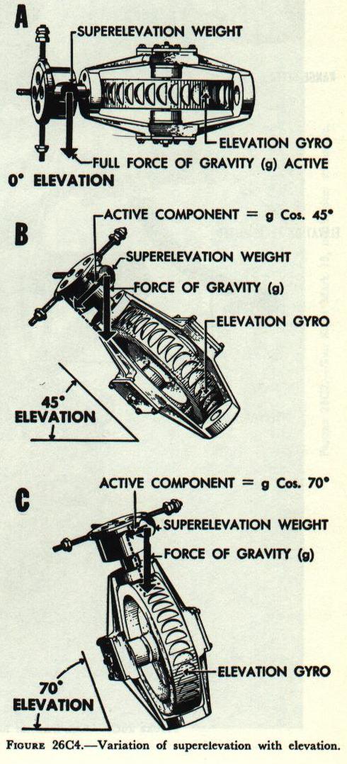 The Gun Sight Mark 15 utilizes two rate-of-turn gyros, one for train (traverse) lead angle and one for elevation lead angle. The gyros are air-driven, and rotate at approximately 8,300 revolutions per minute. Air to drive the gyros comes from an air supply unit associated with the sight, and in order to maintain a constant speed of rotation of the gyro, the air is kept at a constant temperature and pressure. Each gyro rotor is mounted in a gimbal frame which is in turn mounted in the gyro case by a frictionless suspension. The gyro rotors are oriented with their spin axes perpendicular to the fore-and-aft axis of the sight case and to each other, so that the train gyro responds only to motion in the traverse plane and the elevation gyro responds only to motion in the elevation plane. Each gyro痴 output shaft is restrained by a range spring at one end, while on the other end a torque motor is mounted to provide for the introduction of wind ballistic corrections. On the same end as the torque motor are one or more weights for the purpose of making ballistic corrections for drift and superelevation.
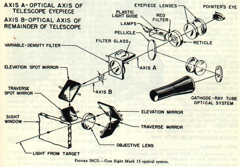 The optical system of Gun Sight Mark 15 includes a telescope, lead angle mirrors, spot mirrors, an optical filter, a reticle plate, and reticle illumination. In addition, some modifications include a cathode-ray tube and a pellicle for introducing its image into the line of sight. The arrangement of the optical system is shown in figure 26C5. The target image, after entering the sight case, is reflected from the elevation lead angle mirror to the traverse lead angle mirror, thence through the telescope objective lens to the deflection spot mirror. From here it is reflected to the elevation spot mirror, and then through the reticle plate to the telescope eyepiece assembly. When either of the gyros precesses, it actuates a linkage to offset the corresponding lead angle mirror, thus deflecting the target image. Since the position of the reticle is fixed, this means that the target image will no longer be centered in the reticle. The sight case must then be moved so as to bring the target image back into the reticle circle. The arrangement of the mirrors is such that the sight case must be offset ahead of the target in order to center the image. This causes the sight case axis to lead the target by the necessary amount of lead angle. In a similar manner, the introduction of spots deflects the target image and necessitates a change in the lead angle.
In preparing Gun Sight Mark 15 for operation, the unit must first be warmed up. The warming-up process requires a period of about 30 minutes for bringing the damping fluid to its operating temperature and viscosity. Bringing the gyros up to their designed operating speed requires about 6 minutes. When operating in an area where attack is likely, the sights are kept warmed up and ready for use.
Preliminary to firing, the target is located by means of a fixed auxiliary telescope mounted on top of the sight. The target is tracked briefly through the auxiliary telescope, after which the operator shifts to the gun-sight telescope. During this initial process the range is kept set at the minimum value in order to restrict movement of the gyro, or, if gyro cagers are installed, the gyros are kept caged. When the target image has been centered in the reticle circle, the cager is released and the proper range and range rate are set in. 羨 similar process is used for radar tracking, except that in this case the auxiliary telescope cannot be used.
Tracking the target or radar spot is continued. The target or spot is kept centered in the reticle circle by smooth movement of the director. It is essential that all tracking movements be smooth, since sudden movements cause the generation of false lead angles.
During tracking, the appropriate values of range and range rate are continually set into the sight. If no radar is provided, estimated ranges must be set in. In this case the range setter should determine whether the range is set correctly by observing the projectile tracers. For an incoming target, which is the usual case, the range should be set initially so that the tracers pass just behind or below the target. Tracers passing behind the target indicate that the lead angles are too small. This is the case when the range setting is less that the actual range, as a short range setting causes the restraining springs on the gyros to be stiff. It is readily apparent that, as the target approaches, the actual range will agree more closely with the set range, and the tracer stream will move toward the target. When the actual and set ranges are equal, the tracers should be hitting the target. As the actual range becomes less than the set range, the tracers will pass ahead of the target, because the generated lead angles are too large. Now the range setting must be decreased to make the tracers again pass behind the target.
Thus the range setting procedure is as follows:
1. Set range so that tracers pass just behind or below target.
2. Wait for tracer stream to pass through target.
3. When tracers are passing ahead of target, decrease range setting and repeat steps one and two.