US NAVY
FIRE CONTROL PAGES
NAVAL ORDNANCE AND GUNNERY
VOLUME 2, FIRE CONTROL
CHAPTER 24
ANTIAIRCRAFT PROBLEM
ANALYTICAL
Chapter 24 Antiaircraft problem analytical
A. Target positioning
B. Ballistic computations
C. Gun positioning
24C1. Summary of sight deflection and sight angle
Any error in gun positioning not accounted for by the preceding discussion can, in theory, be accounted for by the application of a deflection spot (Dj) and an elevation spot (Vj) of suitable size.
Ds=Dt + Dw + Dj-Dfs, where:
Dt is deflection prediction,
Dw is wind deflection correction,
Dj is deflection spot,
Dfs is drift correction.
Vs= Vt+ Vw+ Vj+ Vfm + Vf+ Vu- Vx, where:
Vt is elevation prediction,
Vw is wind elevation correction,
Vj is elevation spot,
Vfm is elevation correction for I. V. variation,
Vu is elevation correction for air density variation,
Vf is superelevation,
Vx is complementary error.
Also, R2, which enters into the determination of the ballistics listed above, may be expressed as:
R2=cR+Rt+Rw+Rj+Rm+Rx+Re, where:
cR is generated present range,
Rt is range prediction,
Rw is range wind correction,
Rj is range spot,
Rm is range correction for I. V. variation,
Rx is change in advance range due to deflection prediction,
Re is change in advance range due to elevation prediction.
24C2. Makeup of gun orders
Under normal conditions, the deck is not horizontal and guns are positioned by gun orders made up in a computer. These gun orders are based on the director LOS; they include Vs and Ds, which must continuously be corrected for inclination of the deck. This correction is known as trunnion tilt correction. Since the gun’s motion is limited to train in the deck plane and to elevation in a plane perpendicular to the deck, gun orders must be computed in those planes and must be based on the standard reference of the ship. Trunnion tilt corrections assume greater importance in AA fire than in surface fire, because of higher gun elevation. These corrections are not included in Vs and Ds, because of the rapidity with which they change, but are computed and included in gun train and gun elevation order.
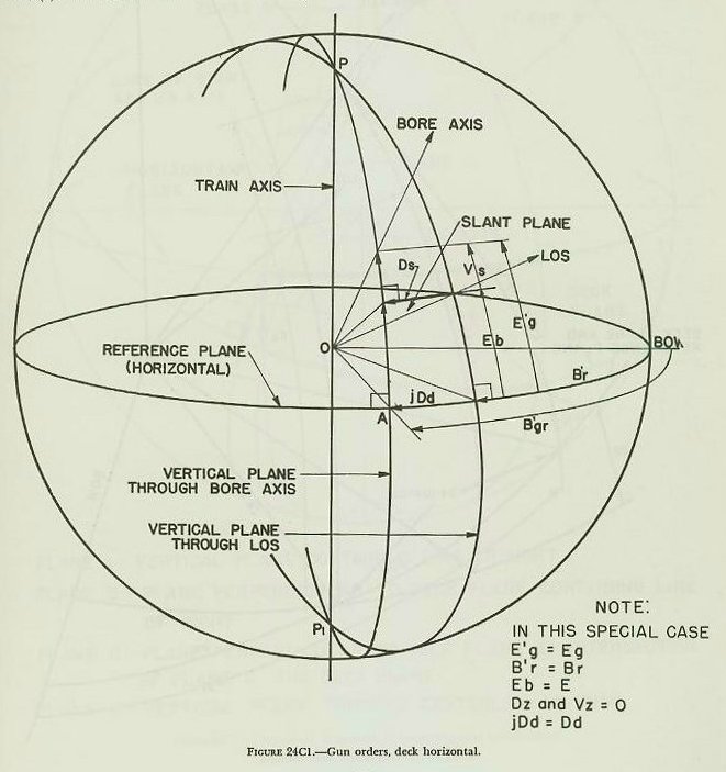
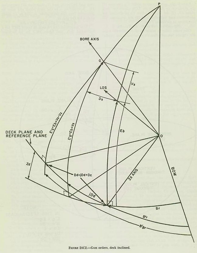
Accordingly, gun elevation order E’g contains (1) the elevation of the director LOS above the deck plane Eb, (2) the vertical offset Vs to account for prediction and ballistics, and (3) the trunnion tilt correction in elevation Vz or,
E’g=Eb+ Vs-Vz=E+L+ Vs-Vz.
Gun train order is made up of (1) director train B’r, (2) the lateral offset Ds to account for prediction and ballistics, and (3) trunnion tilt correction Dz. Actually Ds is in the slant plane and must be projected into the deck plane as jDd to be made usable for the gun or,
B’gr=B’r+jDd + Dz=B’r+ Dd.
These quantities can be seen in figure 24C1 for a horizontal deck, and figure 24C2 for an inclined deck.
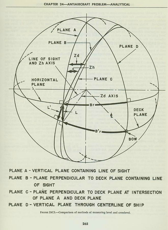
In the stable element, however, the two gimbals are reversed. The crosslevel gimbal is the outer one, and its axis is fixed with respect to the deck. This results in’ the measurement of crosslevel, Zd, about an axis in the deck plane. Since the level gimbal is kept in the horizontal, level, L, is measured in the vertical plane, about an axis in the horizontal. Figure 24C3 shows the difference in the ways the quantities are measured.
This difference in design is made necessary by the difference in design of the director sights. In the main-battery system the sights are not stabilized, and elevation is measured in a plane perpendicular to the deck. In the dual-purpose system, director sights are stabilized as shown in figure 25B6, so that the sighting plane is kept vertical and elevation and level are measured in the vertical plane. Stabilization is necessary because the use of an elevated LOS would introduce large errors if an unstabilized sight were employed. Extensive study of the stable element will be made later.
24C3. Fuze settings
Since the results of the computations of Vs and Ds are, at best, close approximations, AA fire normally uses fuzed projectiles calculated to burst in the vicinity of the target and destroy the target by fragmentation. Time-fuzed projectiles require the calculation of fuze time (F). When VT fuzes are used, the same calculations are necessary, as time fuzed projectiles are interspersed with VT-fuzed projectiles to ensure some bursts, as an aid to improving an inaccurate solution; and in addition mechanical time fuzes are still used with star shells.
If a mechanical fuze could be set and fired at the same instant, a fuze setting equivalent to Tf for the advance position of the target would cause the projectile to burst at the proper time. Actually the fuze is set before the projectile is loaded. The time elapsed between setting the fuze and firing the projectile is called dead time (Tg). Its value, determined by analysis of drills and firings, is usually about 4 seconds. In order to set the fuze Tg seconds before firing and still obtain a burst at the target, it is necessary to predict the value of Tf that will exist when the projectile is fired.
This fuze setting is determined indirectly in the practical solution. To be accurate, both the change in predicted target elevation and the change in advance range during dead time should be accounted for. The change in predicted target elevation is small enough to be neglected. However, change in range is corrected for and may be considered to be TgXdR. This value, combined with R2, gives R3, fuze range. Fuze setting F is based on R3. If, after firing, the time-fuzed projectile is observed to burst behind or ahead of the target, a correction must be applied to F. This normally is accomplished by a range spot, Rj.
R3=R2+(TgXdR).
The fuze setting is the time of flight corresponding to R3.