| NAVAL ORDNANCE AND GUNNERY VOLUME 2, FIRE CONTROL CHAPTER 21 BATTERY ALIGNMENT |
| HOME INDEX Chapter 21 Battery alignment A. Alignment of gun sights B. Train alignment in drydock C. Elevation alignment in drydock D. Battery alignment afloat E. Firing stop mechanisms |
| E. Firing Stop Mechanisms 21E1. General Theoretically the battery is aligned when, with the dials matched and parallax on zero, all the lines of sight and the axes of all gun bores are parallel, regardless of the ordered angles of gun train and gun elevation. In practice, however, the battery check is not complete until: (1) the firing cutout cams in each gun have been plotted, cut, and installed; and (2) the firing stop mechanisms have been checked, with the cams installed, to ensure that both the mechanical and the electrical firing circuits are interrupted properly whenever the guns move from a zone of safe fire to danger zone. The importance of this phase of the procedure cannot be overemphasized. The numerous casualties that have occurred because a ship has fired one of her guns into her own superstructure testify to the seriousness of any misalignment of the firing stop mechanisms. It is equally important to note that in all cases these casualties could have been prevented. They resulted from negligence on the part of the ship’s personnel: the cams were cut improperly and in some cases misaligned, or the firing stop mechanisms were inoperative through lack of preventive maintenance. Firing stop mechanisms are designed to interrupt the mechanical and electrical firing circuits whenever the guns are trained or elevated to a position where firing the guns would endanger ship’s personnel or damage own ship. They should not be confused with the frameworks of steel tubing or depression-stop cams that are used occasionally to limit the movement of light machine guns to safe zones of fire. Firing stop mechanisms do not interfere with the free movement of the gun; this is done by the train and elevation limit stops. The Bureau of Ordnance has issued definite instructions for the guidance of the personnel responsible for plotting, cutting, installing, and checking firing cutout cams and mechanisms. In all cases these regulations must be adhered to strictly. In addition, special instructions govern particular gun installations; for example, the firing limits of 40-mm gun mounts. 21E2. BuOrd regulations for firing cutout cams In accordance with Bureau of Ordnance instructions a firing stop cam installed on any gun shall be so designed that it will prevent firing into fixed structure and into certain other areas under the following conditions: 1. When removable parts of the ship’s structure such as stanchions, handrails, life lines, davits, and equipment such as boats, chests, lockers, and hatches have been removed or stowed so as not to obstruct the line of fire. 2. When, for the firing bearing (azimuth and elevation) under consideration, movable parts such as guns, turrets, cranes, and booms cannot be so disposed of as to clear the line of fire. 3. When, for the firing bearing (azimuth and elevation) under consideration, the personnel cannot be so disposed as to clear the line of fire. Gun firing cutout cams designed in accordance with the above instructions will not restrict the firing of the guns so as to prevent damage to the following: 1. Personnel within the danger blast area of the gun. 2. Material that can be, but has not been, moved clear of the line of fire. In order that firing stop cams may be designed for the maximum possible zone, the Bureau of Ordnance does not approve of cutting firing stop cams to provide protection of forestays, halyards, antennae, and such top hamper. Peacetime target practice must be arranged so as to keep the fire clear of these obstructions. In wartime these hazards must be accepted. For guns of 5-inch and larger caliber a minimum clearance of one caliber shall be maintained between the extension of the axis of the gun bore and the fixed structure. For protection of other installations, this minimum clearance is computed with the other guns and directors at zero-degree elevation and the angle of train at which they are normally secured. For 3”/50 caliber guns a minimum clearance of 5 inches is required, while for 40.mm guns a minimum clearance of 8° must be maintained. This seemingly large clearance for 40-mm guns is due to the lag between the time the cutout mechanism functions and the time that the guns actually cease firing. For 20-mm guns the safe zone of fire must be plotted with the ready-service lockers open. This is necessary because in time of battle these lockers are normally open, or may be open, so that the ammunition can be reached easily. 21E3. Turret firing cutout mechanisms The majority of the main-battery guns of 6-inch bore and larger have separate firing cutout mechanisms for train and for elevation. In train the cam surface is fastened to the stand near the roller path, while the plunger and cutout switch are located on and move with the carriage. Cutout action is obtained by securing cam surfaces to the stand at those relative bearings coincident with the danger zones of fire. The elevation cutout is a fiat cam-and-plunger mechanism mounted on the deck lug of the gun. Movement of the gun in elevation, through a mechanical connection, rotates the cam. On these large-caliber guns only the electrical firing circuit is interrupted by the cutout cams. The percussion firing circuit is not cut out by the cams; however, warning lights are energized in the mount or turret to indicate that the gun is in a danger zone and should not be fired by percussion. The proper settings for these firing cutout mechanisms are outlined in the applicable OP’s. Usually the OP’s will list the settings for the individual turrets in ships of a class. After the cams are in. stalled, they must be checked by the methods similar to those outlined for smaller guns. 21E4. Profile-cam mechanisms Dual-purpose guns, and nonturret guns generally, incorporate mechanisms wherein one cam, referred to as a profile cam, controls the firing circuit when the gun is in or near a danger zone of fire in either train or elevation. This type is used on 40-mm, 3”/50, 5”/38, 5”/54, and some larger-caliber guns. The mechanical action of these mechanisms differs slightly from gun to gun, but in principle they are the same and can be considered collectively. The cutout feature of profile-cam firing stop mechanism is accomplished by the action of a plunger or cam pin on a lever and a circular profile cam. When the plunger rides up on a high point of the cam, which represents a danger or nonfiring zone, it pushes against the plunger lever, which in turn causes sufficient movement of another lever or levers to interpose a break in the firing circuit. In the 5”/38 dual-purpose gun, this movement interrupts both the electrical and the percussion firing circuits. |
 |
 |
 |
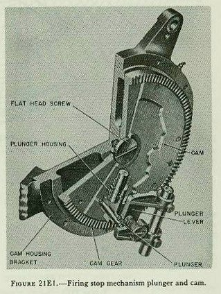
| Figure 21E1 shows a cut-away view of a typical firing stop mechanism plunger and profile cam; this one is from a 5”/54 mount. The cam is turned by gun train order at one-to-one speed, while the plunger mechanism moves radially from near the center to the edge of the cam in accordance with gun elevation order. A point near the center of the cam represents maximum gun elevation, and the outer edge minimum gun elevation. The rise from the cut-away to the raised portion of the cam is inclined to the face of the cam by an angle of 30 degrees. This permits the plunger to ride from the low machined-out surface of the completed cam to the high surface without excessive wear or scoring. Cutout occurs when the plunger is two-thirds of the way up the incline. This must be borne in mind when laying out the cam. It is necessary to scribe two additional lines, besides the line representing the danger zone of fire, on the cam. These lines represent the top and bottom of the incline. 21E5. Plotting the cams The entire firing stop mechanism, with the exception of the profile cam, is assembled and installed on the mount during manufacture. As the profile of the cam will vary with the location of the gun, the cam must be plotted after the gun is installed aboard ship. The precise method of plotting the cam depends upon the type of gun. One of the methods which can be used for a 5”/38 gun will sufficiently illustrate the principles of the operation. |
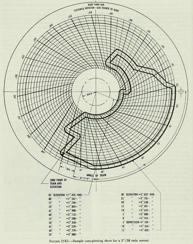
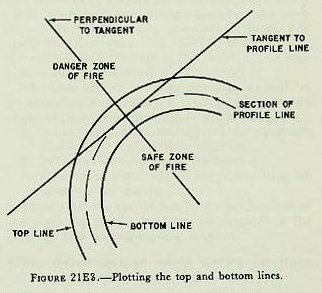
| This method consists of mapping out the zone of permissible fire by means of a boresight in the bore of the gun, plotting the minimum safe angles of elevation at successive angles of train on a cam-plotting sheet, and transferring the plot to the cam blank. Cam-plotting sheets, such as illustrated in figure 21E2, are available at all naval shipyards. It is important to note that plotting sheets are made for each specific caliber mark, and modification of gun, and that right and left guns of a twin mount use different sheets (one cam turns clockwise, the other counterclockwise). Before transferring the plot to the smooth copy of a plotting sheet, it is in each case necessary to consult the OP or OD for the particular type of mount. This will contain such information as the minimum radius of all curves in the plot, the radial distances of the top and bottom of the cam slope from the actual cutout line (see fig. 21E3), and other data essential to accurate plotting. It should be noted that, in tracing the safe-fire zone of any mount with more than one gun, a separate cam must be plotted for each gun (each pair of barrels in the case of the 40-mm only). Thus one gun may stop firing upon training toward the edge of an obstruction while the other gun or guns will continue to fire until the mount has been trained a few degrees more toward the ship’s structure. |
| 21E6. Final steps After a cam has been plotted by any one of the methods listed, it is turned over to the yard for machining. When the machine work is completed and the cam is returned to the ship, it must be installed and synchronized according to the instructions contained in the ordnance publication pertaining to that type of gun. Finally the accuracy of the cam profiles and the adjustment of the firing stop mechanism must be checked. The following is a suggested procedure; however, the voltmeter recommended can be replaced by an electric lamp of the correct voltage rating, if desirable. 1. Make sure that the gun is not loaded. 2. Lay the gun so that it is outside of a danger zone. 3. Complete the firing circuit as for local firing. 4. Connect a suitable standard voltmeter between the firing pin and ground, or across the terminal of the firing-cutout switch. 5. Firing-circuit voltage should be indicated by the voltmeter, thus establishing continuity of the circuit. 6. Lay the gun so that it is within a danger zone. The voltmeter should now read zero. 7. Train and elevate the gun in and out of the firing zone, at various points, verifying that the operation of the firing stop switch, as indicated by the voltmeter, takes place at the proper points. 8. If percussion firing is also included in the cutout mechanism, check to see that percussion firing cuts out at the same points as those at which the switch in the firing opens. If a voltage is present in step No. 6 or during those parts of step No. 7 when the gun is in a danger zone, a defective firing stop switch, a defective or short-circuited plug, or faulty cable insulation is to be suspected, and immediate steps must be taken to locate and correct the defect. The preceding section on firing cutout cams has briefly presented the theory of these mechanisms, but when it comes to plotting and cutting the cams, remember this: always consult the OP; there is no substitute for exact knowledge. |