| NAVAL ORDNANCE AND GUNNERY VOLUME 2, FIRE CONTROL CHAPTER 19 SURFACE FIRE CONTROL PROBLEM |
| HOME INDEX Chapter 19 SURFACE FIRE CONTROL PROBLEM A. General B. Analytical solution C. Graphic rangekeeping D. Mechanical solution-general E. Basic mechanisms F. Mechanical solution-basic rangekeepers G. Mechanical solution-establishing the horizontal plane |
| G. Mechanical Solution-Establishing the Horizontal Plane 19G1. Introduction Guns are installed with their roller paths parallel to the deck plane, so that their movement is limited to train in the deck plane and elevation above the deck plane. On the other hand, Vs and Ds are computed with reference to the horizontal. Since the deck plane of a moving ship deviates from the horizontal by the amount of roll and pitch, some means must be found to measure and correct for this discrepancy. Correction for deck inclination is most satisfactorily applied in the solution of the fire control problem if it is resolved into components in planes in and across the line of sight. The component in the line of sights, called level, then becomes a modification to elevation; while the component across the line of sight, called crosslevel, affects both train and elevation, as it causes the trunnions of the guns to tilt. In early director systems the pointer’s telescope established the line of sight and a crosslevel telescope at right angles to it was kept on the horizon. The amount these telescopes had to be elevated or depressed from their zero position measured the tilt of the deck, and was applied as a correction within the rangekeeper. This method is used as a standby procedure in one modern system. It is fairly satisfactory, but is subject to human error, and is useless when the horizon is not visible. Modern surface systems use, as their primary method of measuring level and crosslevel, an instrument called a stable vertical, which is essentially a gyroscope equipped with suitable mechanical and electrical pick-offs. The instrument establishes and maintains the true vertical and its associated horizontal plane, continuously measures level and cross-level, and transmits these values mechanically and electrically to the Mark 8 rangekeeper. 19G2. Gyroscopic principles To understand the action of the stable vertical, it is necessary to understand the principles of the gyroscope. Any rapidly spinning mass will show the characteristic properties of a gyroscope. But for simplicity this discussion will be confined to a wheel, spinning rapidly on its axis. A rapidly spinning wheel shows two properties that make it especially useful in fire control instruments. One of these properties is rigidity in space. This means simply that a wheel, as long as it is spinning rapidly, tends to keep its axis pointed in the same direction in space. (Because the earth itself is spinning, the wheel will not necessarily tend to keep its axis pointed in the same direction with respect to the earth’s surface. This is explained in article 19G4.) A spinning top shows a good example of gyroscopic action. When it spins at high speed, the top remains erect, keeping its axis vertical. As the speed dies down, the axis is no longer able to maintain a fixed direction in space; the top begins to wobble, and eventually falls over. A bicycle wheel is another familiar example. Because of gyroscopic action, a bicycle is more easily balanced at high speed than when it is moving slowly. Another name for the principle of “rigidity in space” is gyroscopic inertia. The inertia of the spinning wheel is the cause of its gyroscopic action. To understand this, consider the effect of inertia on any point on the wheel’s rim. The law of inertia states that when any body is in motion, it will continue indefinitely to move in a straight line, at the same speed, unless acted on by some external force. Any point on a spinning wheel is moving in a circular path. Because of its inertia, such a point will tend to move in a straight line, tangent to its circular path. But molecular attraction within the wheel tends to hold the particles together, and at normal speeds will confine all particles in the wheel to circular paths. (However, any wheel will fly apart if it is spun with sufficient speed.) The inertia of all the particles in the wheel, then, will tend to keep these particles moving in circular paths, with the result that the wheel tends to keep spinning in a single plane, and its axis tends to point in a single direction. The wheel will maintain its plane of rotation, and the axis will maintain its fixed direction, until the system is acted on by some outside force. The inertia of a spinning wheel, and therefore the reliability of its gyroscopic action, depends on two things: the mass of the wheel, and the speed with which it is moving. For that reason, a gyroscope is relatively heavy, and is rotated at high speed. The speed of any particle on the gyroscope wheel depends not only on the speed of rotation, but also on the distance of the particle from the center. For that reason the weight of a gyroscope wheel is usually concentrated in its rim. Another useful property of a gyroscope is precession. This term refers to the manner in which a gyroscope responds to any force that tends to change its plane of rotation, or the direction of its axis. When the speed of a spinning top decreases, gravity tends to pull the top down, and turn its axis horizontal. The top responds to the force of gravity by moving its axis at a right angle to the applied force. The resulting wobble is an example of precession. Another example may be seen when a high-speed electric fan is turned about a vertical axis. The resulting precession tends forcibly to turn the fan at a right angle to the applied force, moving the blades toward a horizontal plane. (Unless the blades are well enclosed, this is a dangerous experiment.) |
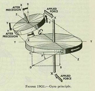 |
| A study of figure 19G1 will show that precession, like rigidity in space, is a result of inertia. Imagine that the larger wheel in the figure is spinning rapidly, in a direction shown by the arrow on its rim. If a force is applied that tends to move the wheel in its plane of rotation, or along its axis, no precession will result, since such forces do not tend to change the direction of this axis. But consider a force that tends to change the direction of the axis. Such a force is represented by the two arrows, marked “applied force.” If the wheel were not spinning, this force would turn the wheel about the axis Y-Y. However, since the wheel is spin-fling rapidly, it responds to the applied force by precessing-by moving its axis in a direction at 90 degrees from that of the applied force. To understand this action, consider the forces acting on the point marked “A,” at the instant represented by figure l9Gl. The inertia of this moving point tends to carry it in the direction AC. The applied force tends to move point A in the direction AB. Assume that in the diagram the lengths of these two lines, AC and AB, are proportional to the respective magnitudes of the two forces. Since the point A can not move in two directions at once, it must respond to the two forces acting on it by moving in the direction AD. The direction and length of the line AD represents the direction and magnitude of the resultant (vector sum) of the two forces acting on point A. Obviously, point A can move in the direction AD only by turning the wheel’s plane of rotation to the position shown in the smaller diagram of figure I 9G1. So far, the discussion has been confined to the action of the single point A. A further study of the diagram, however, will make it apparent that at any given instant, every point on the wheel (with the exception of points on the axis Y_Y) will be acted on by two separate forces. In every case, the vector sum of these two forces is such as to turn the plane of rotation in the direction shown in the smaller diagram. Precession, then, results in a movement of the axis in a direction at 90° from that of the applied force. As a result of precession, the axis of rotation (X-X), tends to become parallel to the axis of torque (Y-Y). Precession will continue until the applied force is removed. Inspection of figure 19G2 will provide a ready means of determining direction of precession. If a downward force is exerted on the gyro case as shown (at north) a gyro rotating clockwise will precess in the direction indicated (to the east). |
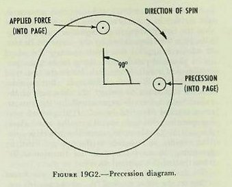 |
| Since level and crosslevel are angles measured between the reference plane and the true horizontal, the stable vertical accomplishes this measurement by containing a free gyro mounted inside an instrument case. The case itself is bolted to the deck in such a way as to be exactly parallel to the reference plane. Then, with the gyro maintaining its spin in the horizontal, the differences between the position of the gyro and the reference plane are measured and applied as needed. 19G3. Righting system The gyro wheel is made to assume a horizontal position while spinning, and to maintain its original plane of rotation, by means of a mercury control system which opposes any external force tending to displace it. Essentially the mercury control system consists of two tanks containing mercury, attached to the casing which houses the gyro wheel, on diametrically opposite sides of the wheel. These two tanks are joined by a narrow connecting tube, so that mercury is free to flow from one tank to the other. As long as the gyro wheel is exactly horizontal, the mercury level in both tanks will be the same; but as soon as the wheel is tilted from the horizontal by some external force, gravity will cause mercury to flow from the high tank to the low tank. The additional mercury in the low tank will then produce the same effect as a downward pressure exerted at the low point of the gyro wheel. Application of the rule of precession (fig. 19G2) shows that this will only cause the wheel to precess more out of the horizontal in a direction 90° away. However, if the mercury effect is applied not at the low point but 90° from the low point, pressure at this point causes the low point of the gyro to precess upward to its original horizontal position, at which point the mercury is redistributed equally. This effect is accomplished in the stable vertical by rotating the entire gyro assembly and attached mercury tanks at 18 rpm in the same direction as gyro spin, and by restricting the size of the orifice to regulate the flow of mercury in the connecting tube. The net result is that by the time the mercury has reached the low tank, the low tank has been displaced 90° from the low point of the gyro wheel, and the pressure exerted here causes the gyro spin axis to precess back into the vertical. It should now be apparent that when the gyro is first started, exactly the same action takes place to cause the gyro spin axis automatically to erect itself and settle in the vertical, after several minutes of operation. |
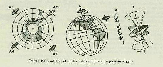 |
| 19G4. Effect of the earth’s rotation Further consideration will indicate that the horizontal plane necessary for purposes of fire control is a plane tangent to the earth’s surface at the ship’s position. A gyroscope originally set in this plane will not remain in the horizontal, as the earth rotates, unless some means is provided to compensate for the effect of earth’s rotation. A gyro located at either pole will be unaffected, as the plane tangent to the earth at these points remains fixed in space. On the other hand, a gyro located at the equator will assume the successive positions with respect to the earth shown in figure 19G3 (A). To an observer standing on the earth, the wheel will turn completely over every 12 hours; that is, turn backward with respect to the earth’s rotation at the rate of one revolution in 24 hours. At any point between the pole and the equator, as shown in figure 19G3 (B) the wheel gyrates once every 24 hours about an axis parallel to the axis of the earth’s rotation and in a direction opposite to that of earth’s rotation. This effect can be compensated for if the gyro can be made to precess slowly to the eastward at the same rate as the earth’s rotation. The gyro’s plane of rotation will then remain parallel to the horizontal plane. This is accomplished in the stable vertical by means of a latitude weight which is so arranged that the effect of the weight is to cause a downward pressure at the north point of the gyro wheel, resulting in an easterly precession. The position of the latitude weight is adjustable, so that it can be set for the latitude in which the ship is operating. Actually, the mercury control system would tend to keep the gyro spin axis vertical, but if the mercury control were acting alone, the gyro would still tend to deviate slightly from the vertical as a result of the apparent precession caused by the earth’s rotation. The latitude weight compensates for this error. |
 |
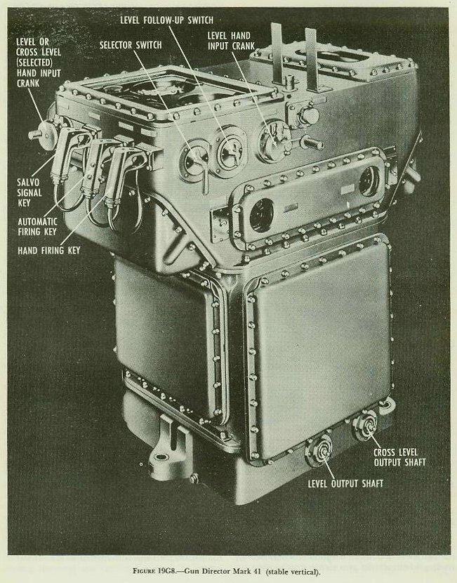
 |
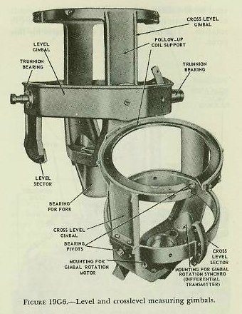 |
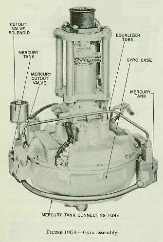
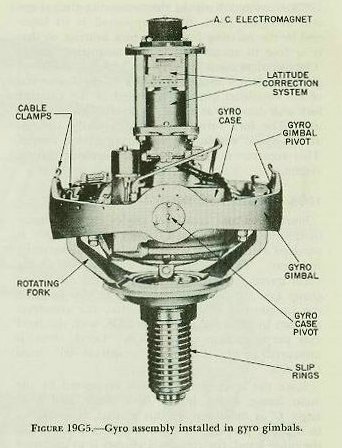
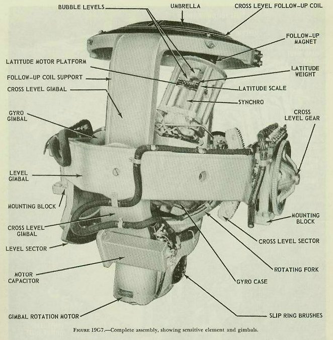
| 19G5. Mechanical construction The Mark 41 stable vertical consists essentially of a sensitive element and a measuring group. The sensitive element is the heart of the instrument and consists of the gyro, gyro case, gyro gimbal, and a fork-shaped support known as the rotating fork. Figure 19G4 shows the gyro proper. The wheel is carried on an axle supported by ball bearings at the upper and lower ends of the gyro case, the wheel and case forming the rotor and stator of a high-frequency induction motor. The squirrel-cage winding, consisting of solid conducting bars, is in the gyro wheel, while the wire stator windings are in the gyro case. A special motor-generator is provided to supply power at a frequency sufficient to drive the gyro at about 8,500 revolutions per minute. The gyro assembly of figure 19G4 pivots within the gyro gimbal on a case axis perpendicular to the spin axis, as shown in figure 19G5. The gimbal ring, in turn, is supported by the arms of the rotating fork on the gimbal axis, which is perpendicular to both the case axis and the spin axis. This axis arrangement provides a universal mounting giving the gyro three degrees of freedom, and allows it to spin on a vertical axis, even though the rotating fork may vary its from time to time. The measuring group consists of a level gimbal, a crosslevel gimbal, and a training gear. Figure 19G6 shows the arrangement of the measuring gimbals. The outer gimbal is he level gimbal, supported at its trunnion bearings by the training-gear structure (main frame). The level gimbal, in turn, supports the inner or crosslevel gimbal, so that its axis is perpendicular to the level-gimbal axis. At the lower end of the crosslevel gimbal the bearing for the rotating fork can be seen. The entire sensitive-element assembly of figure 19G5 is mounted within the measuring-gimbal system of figure 19G6, being supported at its lower end by the rotating fork in its fork bearing, so that it is free to rotate within the measuring group. The complete assembly is shown in figure 19G7. A gimbal rotation motor, attached to the lower end of the crosslevel gimbal, is geared to the rotating fork and drives it at about 18 revolutions per minute. The fork turns the entire sensitive element at this speed within the measuring-gimbal system. This rotation is essential to the mercury control system. |
 |
 |
| 19G6. Director train input Since level and crosslevel angles must be measured with respect to the LOS, director train B’r’ is received at the stable vertical to position the training gear. The training gear carries with it the main frame, which in turn supports the measuring group and the sensitive element. In this manner, the instrument is so oriented that the crosslevel axis lies in the direction of the LOS, with the level axis perpendicular to the LOS. Level, then, is measured in the LOS, and crosslevel 90° from the LOS. Since the level gimbal axis is supported by the main frame, it lies in the deck plane, and level angle L’ as measured by this gimbal, is measured in a plane perpendicular to the deck plane. On the other hand, the crosslevel gimbal is so mounted that it remains in the horizontal and measures cross-level angle (Zh) in a vertical plane. These features of construction cause the stable vertical to measure L’ and Zh in accordance with the definitions of article l9F2l. 19G7. The follow-up system The actual measurement of L’ and Zh is accomplished by an electrical follow-up system. Figure 19G5 shows an electromagnet installed at the upper end of the gyro spin axis. This magnet remains in the true vertical because of the action of the gyro. Above the magnet but attached to the top of the crosslevel gimbal is an umbrella containing two figure-eight follow-up coils at right angles to each other, one for level and the other for crosslevel. |
| Roll or pitch of the ship will cause movement of the umbrella with respect to the magnet, inducing voltages in the follow-up coils by transformer action. The voltages so induced are amplified and rectified at a stable-vertical control panel, and are then used to energize level and crosslevel follow-up motors, which drive back through the gear trains, causing the level and crosslevel gimbals to move. When the umbrella is back in its neutral position over the electromagnet, voltages are no longer induced in the coils and the follow-up motors cease to drive. The follow-up coils are so constructed that they pick off voltages proportional to L’ and Zh, respectively. The amount of rotation of the follow-up motors necessary to cause the gimbals to maintain the umbrella at the neutral point over the electromagnet is then a direct measure of level and cross-level. These outputs are transmitted electrically and mechanically to the instruments requiring these values. The response of the follow-up system is made sufficiently sensitive to cause the umbrella center to remain very nearly in line with the magnet. The motors drive practically as soon as displacement begins, so that the measurement of L’ and Zh is continuous and almost instantaneous. An anti-hunt unit is installed at the control panel, and operates to shut off the power to the motors slightly before the neutral position is reached, preventing the umbrella from over-running the neutral position and driving back toward it again. 19G8. Mercury cut-out valves The mercury control system has already been described. It normally operates to keep the gyro axis in the vertical. At times, however, certain irregularities of ship motion, such as sharp turns and speed changes, occur which would cause an irregular flow of mercury, tending to disturb the gyro rather than to right it. To prevent mercury flow at such times, a mercury cut-out valve closes, blocking the connecting tube. This valve is operated automatically by a cut-out control on the control panel. During starting, the valve should remain open and therefore is made inoperative, since ship motion has no appreciable effect on the settling of the gyro. After the gyro has settled, the valve is connected to the automatic control. 19G9. Latitude motor input It will be recalled that the latitude weight must always apply its downward force at the north point of the gyro wheel, and that the amount of force of the gyro wheel, and that the amount of force must be varied in accordance with the ship’s distance from the equator. This is accomplished by manually moving the latitude weight inward or outward in its mounting. It is usually considered sufficient to make a latitude setting once a day. The sensitive element continuously rotates at 18 rpm, and the entire assembly is oriented to the LOS by B’r’. Since the latitude weight is mounted at the upper end of the gyro spin axis as shown in figure 19G5, provision must be made to cancel out the effects of the rotation and the B’r’ input. This is done by mounting the latitude weight on the rotor of a synchro known as the latitude motor. The stator rotates in accordance with the inputs of 18 rpm and B’r’, but the rotor carrying the latitude weight is positioned by a signal impressed on the windings of the stator. This input signal is made up of Co+B’r’±18 rpm, with the result that the rotor keeps the weight positioned in the north-south plane. The input is obtained by combining the stable-vertical inputs of Co and B’r’ in a differential generator to get an output of Co+B’r’. This output is then combined in a second differential generator with 18 rpm from the gimbal-rotation motor, to give Co+B’r’±18 rpm, which is used as the input to the latitude-motor stator. 19G10. Manual follow-up The L’ and Zh follow-up motors normally keep the umbrella positioned automatically over the gyro axis. Usually, then, the level and crosslevel hand input cranks are disengaged and the L’ and Zh follow-up switches are set at AUTOMATIC. Should either follow-up motor fail, the appropriate follow-up switch is set at MANUAL and its associated hand crank is engaged. This action breaks the circuits to the follow-up motor and transfers the umbrella’s pick-off signal from the amplifier unit to the galvanometer shown on the face of the instrument. The hand crank is then turned, to reposition the gimbal and umbrella over the magnet by keeping the galvanometer needle as nearly as possible in its zero position. Manual follow-up can be used instead of either or both follow-up motors. |