| NAVAL ORDNANCE AND GUNNERY VOLUME 2, FIRE CONTROL CHAPTER 17 EXTERIOR BALLISTICS |
| HOME INDEX Chapter 17 Exterior ballistics A. Forces Affecting Trajectories B. Range Tables C. Practical Application of Range Tables D. Target-practice Post-firing Analysis |
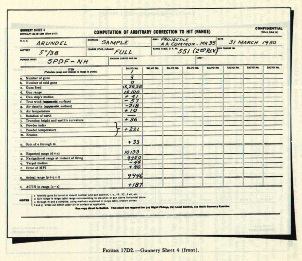
| D. Target-Practice Post-Firing Analysis 17D1 Gunnery Sheet 4 A complete analysis is normally made after each target-practice firing, covering all conditions and matters affecting the practice. Such an analysis will determine errors and, when compared with similar firings by other vessels, will furnish valuable information affecting design of material and improvement of both ordnance material and gunnery procedures. One important goal of post-firing analyses, and the one of primary interest at this time, is determination of the arbitrary correction to hit, which was defined in section 17C7. In order that no factors which affect the ACTH be overlooked, standard procedure has been prescribed to determine its value, and standard forms to record the results are used. The standard form used to compute and record the arbitrary correction to hit in both range and deflection is Gunnery Sheet 4, shown in figures 17D2 and 17D3. This sheet accompanies the post-firing analysis report and forms a part of the permanent record of a target-practice firing. A work sheet, figure 17D1, is used in conjunction with the finished smooth Sheet Four. See footnote on page 55. |
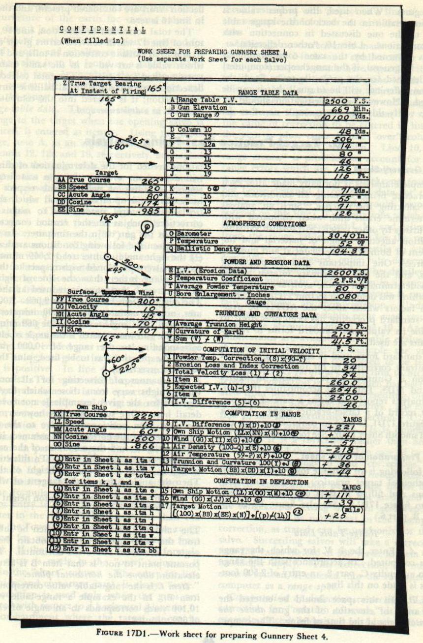 |
| 17D2. Preparation of work sheet The following is an example for the first salvo of a hypothetical target practice, starting with computations and filling in data on the work sheet. Refer to figure 17D1. (See also figure B3 in appendix B, part 6.) Range-Table Data Item A. Enter the I. V. for which the range table is computed. In accordance with the range table in appendix C, part 2, an entry of 2,500 foot-seconds is made on this line. Item B. In this space should be entered the actual angle of elevation of the gun above the horizontal plane at the time of firing. The computations needed for the determination of this value will depend on whether the gun was fired with respect to a line of sight or with respect to the horizontal, and upon the method which the particular fire control system uses to make certain corrections, such as whether erosion correctors are located at the gun or in the computer. In the example given the following conditions are assumed: (1) the sight-angle counter read 2,669 minutes, (2) the guns were positioned with respect to the horizontal plane rather than the line of sight, and (3) no erosion correctors were used at the guns. The entry in item B is therefore 2,669-2,000 minutes, or 669 minutes, since 2,000 minutes represents zero sight angle. (The value 669 minutes to which the gun was elevated is the angle of elevation corresponding to the range of 10,000 yards, at which the practice was to be fired, plus the total ballistic correction.) The manner of correcting for all conditions which might vary from those which have been assumed for the given example is not covered in detail here. One such example, however, is: had the guns been positioned relative to the line of sight instead of the horizontal, as assumed, it would be necessary to find the curvature of the earth for the range from a suitable table. To this curvature would be added the trunnion height of the gun. Then the angle is found, the tangent of which is: curvature of earth + trunnion height / range in feet The value of this angle would then be subtracted from the value 2,669 minutes to obtain the actual angle of elevation above the horizontal. The important point to note is that item B is actual gun elevation above the horizontal plane. Item C is the range-table value corresponding to item B. In the example a range-table value of 10,100 yards corresponds to an angle of elevation of 669 minutes. Items D through N are taken directly from the proper columns of the range table, entering with the value of item C. Tabulations are made to the nearest yard. Note that item K is entered on Sheet 4 as item V. (Item F does not appear in some range tables. Disregard the correction for variation in air temperature if this is the case.) Atmospheric Conditions Item 0 and P, 30.40 inches and 52 degrees F. in the example, are surface readings from ship’s instruments. Item Q. As explained in article l7B6, data for this item may be determined from measured data aloft or from an estimate made by an experienced aerologist. In this example, an entry assumed to be from such a source has been made. If such data are not available, this item is left blank and a nomogram is used for item 11 below. Powder and Erosion Data Item R is the initial velocity used as a basis for velocity loss, in this example it is the nominal I. V. of a new 5”/38 caliber gun using a full charge, 2,600 foot-seconds. Item R does not have to be the same as item A. For the reasons pointed out in article 17B3, the range table is based on an I. V. of 2,500 instead of on the nominal initial velocity. Item S in the example is taken as 2 foot-seconds for each degree Fahrenheit. For an actual practice, a more accurate temperature coefficient should be used as determined from OP 1004 or from the erosion data. Item T is normally the average temperature of the magazines from which the powder is drawn, in this case taken as 80 degrees Fahrenheit. Item U. Here is recorded the bore enlargement in inches obtained in the same manner as described above in connection with the work sheet for the computation of the initial ballistic correction. In the example, the figure is 0.08 inches. Trunnion and Curvature Data Item V, the average trunnion height above sea level, is obtained from the ship’s drawings. Item W is obtained from a table, entering with the argument range. Such a table is contained in Ordnance Circular Letter F8-43. If the letter is not available, the value can be computed from the dip table in Bowditch. Target, Wind, and Own-Ship Data The line-of-sight diagram is covered in detail in section 17C. Three spaces are provided on the work sheet for indicating by vectors the target, wind, and own-ship motion relative to the true bearing of the target. In each case, the line already drawn represents true target bearing. The direction north, relative to true target bearing, is indicated by drawing an arrow through the dot in the circle in the upper right-hand corner of the wind square. The acute angles CC, HH, and MM, are the acute angles between direction of motion of target, wind, and own ship respectively, and the true bearing of the target at the instant of firing. Values of the cosine and sine may be obtained from mathematical tables of trigonometric functions (appendix D), and tabulated to three places. Target data. Motion of the target in no way affects the trajectory or flight of the projectile. During time of flight, however, if the target is under way it moves from the position it occupied at the instant of firing. Target motion toward own ship will decrease the range, while target motion away from own ship will increase the range. If the target moves across the line of sight toward the right, it will change position to the left. In the example target motion, true course 265°, speed 20 knots, is shown with respect to the line of true target bearing. Direction of motion is toward own ship (-) and to the right (+). Wind data. Either “surface” or “upper air” should be crossed out. The upper-air (ballistic) wind should be used when the maximum ordinate exceeds 3,000 feet and accurate aloft winds are available. At other times surface wind is used. In the example, as indicated by reference to column 8 of the range table, the maximum ordinate is less than 3,000 feet. Since FF is true course of the wind, the wind vector will be drawn “down wind.” The effects of wind for the example shown, true course 300°, velocity 10 knots, will cause a short (-) and a right (+) error. Own-ship data. The motion of own ship imparts component horizontal velocities to the projectile in proportion to the components of own-ship motion in and across the line of fire. In the example the vector representing own-ship motion with respect to the true target bearing, true course 225°, speed 18 knots, indicated an over (+) and a right (+) error. Computation of Initial Velocity Item 1 is the error in I. V. due to a variation in powder temperature from 90 degrees Fahrenheit. It should be noted that if temperature is greater than 90° F., the sign is minus, even though an increase in range results. The reason for this is not obvious, but a study of item 1 in conjunction with items 2 and 3 will clarify it. Item 2 is always a velocity loss (since erosion never increases the I. V.). The effect of a powder temperature above 90° F. will reduce this loss, while a powder temperature below 90° F. will increase the loss. Item 3, which is the algebraic sum of items 1 and 2, will therefore be of the correct sign if powder temperature correction is treated as described above. Should item 3 come out with a minus sign, it would indicate a velocity gain. Such a case could occur with a new gun when firing powder from a magazine the temperature of which was above 90 degrees Fahrenheit. This will rarely happen. Item 2. The entry 34 foot-seconds represents the I. V. loss due to a bore enlargement of 0.080 inch. The manner in which this value is obtained was discussed in articles 17C8, 5D5, and 5D6. Items 4, 5, 6, and 7 are self-explanatory. Computation in Range The computation in range for items 8 through 14 is carried out in accordance with the instructions on the work sheet. It is important that the proper signs be used, so that, when these items are transferred to Sheet 4 in accordance with the instructions in the lower left-hand corner of the work sheet, the correct value of expected range will result. If ballistic density has not been obtained and entered in item Q, the value to be entered as item 11 will be obtained directly from the nomogram instead of from the stated formula. Computation in Deflection Items 15, 16, and 17 are filled in with data worked out in accordance with the instructions contained on the work sheet. The proper signs can be determined by reference to the vector diagrams. The value p, used in the formula for item 17, represents the navigational range at the instant of firing, as recorded on Sheet 4. This is the most accurate value of range that can be obtained at the time of the post-firing analysis. As will be noted in the formula, it must be adjusted for target motion by use of item 14. Computation of ACTH After completion of the work sheet for Sheet 4, actual computation of the sheet will be undertaken. Refer to figures 17D2 and 17D3. (See also figures B4 and B5 in appendix B, part 6.) Items 1 through 12, in the lower left-hand corner of the work sheet, contain instructions for transferring entries from the work sheet to Sheet 4. 17D3. Computation of arbitrary correction to hit (range) |
 |
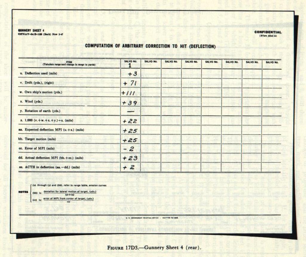 |
| The first lines on Sheet 4 are for identification purposes and in general are self-explanatory. The heading of the space named “run” should be changed to “projectile” and the latter identified by type, mark, and modification. Item a, “number of guns,” refers to the number of guns actually fired. If, for example, a six-gun salvo was intended but due to a casualty only five guns fired, the proper entry is 5. In item b, “number of cold guns” is entered the number of guns firing their initial round since last cleaned and oiled. In the example it is considered that the practice for which the Sheet 4 is being worked out was not the first practice fired that day. The entry here is therefore zero (the correction for the first salvo has been discussed in article 17C7). Had “cold guns” been used in the practice and such a correction applied, item C of the work sheet (and item d of Sheet 4) would then contain this correction and the range-table values for items C through N of the work sheet would correspond to the corrected range. As an example, if a first-salvo correction of +200 yards were used, item C would then read 10,300 yards and the gun elevation, item B, and also items D through N, would have had different values from those shown. Item c, “guns fired,” identifies guns by turret or mount number and gun position. The right guns of mounts 1, 2, and 3 were fired in the hypothetical practice which is being considered. Items d, e, f, g, and h are obtained from the work sheet. Entering values with the proper sign is important. Item i is zero in the example, since, as was pointed out in article l7C8, this correction is omitted for guns of 5-inch and smaller caliber. Items k, 1, and m. The total for these items is combined in the computations on the work sheet. Although the computed I. V. of 2,546 foot-seconds would cause a decrease in range from values taken from a 2,600 foot-second range table, it does cause an increase in the range values taken from the 2,500 foot-second range table which is being used in computing values in the example. Therefore, the sign is plus for this entry of 221 yards. Item o, the expected range, is the gun range corrected for all known variations from standard range-table conditions which affect the projectile in flight, plus trunnion height and earth’s curvature. It should be noted that the target motion does not enter into this computation, because the value of expected range applies to the point of fall of the projectiles and is to be used for comparison with the actual range to the point of fall. Item p is the navigational range at the instant of firing. The most accurate and carefully calibrated radar should be used to obtain this figure. If no more accurate data are available, the present range of the computer solution should be entered. Item q is obtained from the work sheet, using care in selecting the proper sign. Since in the example the target is closing, the range will decrease during the time of flight of the projectile. Item r, the error of MPI, represents the actual difference between the position of the target at the instant of the fall of the projectiles and the mean point of impact of the several shots. The precise definition of MPI, mean point of impact, and the method of computing it from the points of impact of the several individual shots, are discussed in chapter 18. For this use in post-firing analysis, the best available data on the points of fall of individual projectiles should be used. When a camera party is available, these best data are obtained by triangulation of aerial photographs. Overs carry the (+) sign; shorts, (-). An arbitrary value of +40 for error of MPI is used in figure 17D2. Item s, it will he apparent by inspection, represents the actual range, to the point of fall, of the projectiles fired. Item t, therefore, represents the otherwise unaccounted-for errors, the average value of which for several complete practices may be used as ACTH in range. 17D4. Computation of arbitrary correction to hit (deflection) Item u is the difference between the midpoint of the deflection scale and the actual scale reading. It is the number of mils between the plane through the LOS and the plane through the bore axis at the instant the gun was fired. The sign is (+) if the scale reading is to the right of the midpoint and (-) if to the left. In the example the scale reading was 503. Items v, w, and x-71, 111, and 39 yards, respectively in this example-are taken from the work sheet. The proper sign is important. Item y is similar to item i and its value is zero in this example for the reason previously given. Item z, it will be noted, includes a conversion from yards to mils at the actual range. Item aa, the expected deflection, consists of the deflection used, corrected for drift and for those variations from standard range-table conditions which affect the projectile while it is in the air. This item serves the same purpose in deflection as item o in range. Item bb is obtained from the work sheet. Item cc is the error of the MPI in mils, obtained by photo triangulation or observation. If the MPI is right of the target the sign is (+), if left (-). In the example, the error of the MPI was 2 mils left. Item dd is the actual deflection of the MPI in mils. It is the perpendicular distance (converted to mils) from the vertical plane through the line of sight to the mean point of impact. This item is the deflection equivalent of item s above. Item ee, the ACTH in deflection, is obtained by subtracting item aa from item dd. Like item t in range, it represents the errors otherwise unaccounted for. These two values ACTH in range and deflection represent the two values which, as stated above, are to be found through the processes of post-firing analysis. |