| GENE SLOVER'S US NAVY PAGES NAVAL ORDNANCE AND GUNNERY VOLUME 1, NAVAL ORDNANCE CHAPTER 14 ANTISUBMARINE WEAPONS |
| HOME INDEX Antisubmarine Weapons A. Antisubmarine warfare B. Depth charges C. Depth bombs D. Throwing weapons E. Nets and booms |
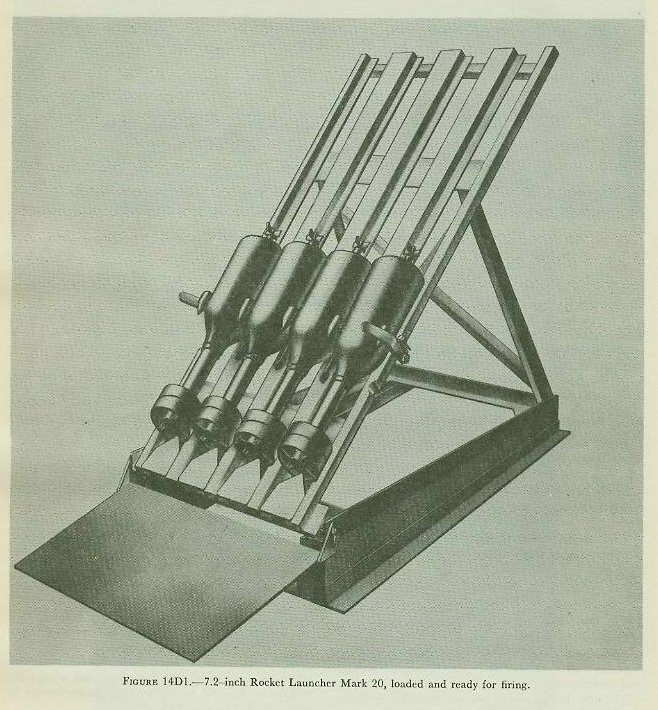
| D. Throwing Weapons 14D1. The 7.2-inch rocket Chapter 11 described the solid-nose 3.5-inch rocket, which is used as an airborne antisubmarine weapon. Surface craft may also carry antisubmarine rockets and rocket-type missiles. The first thrown missile put in service by the Navy was the 7.2-inch rocket and its associated Rocket Launcher Mark 20, illustrated in figure 14D1. Two such launchers, mounted on the forecastle of an antisubmarine vessel, can fire a pattern of eight charges. Since the charge is a true rocket, there is negligible thrust against the deck when a pattern is fired; thus this weapon is suitable for use on such small craft as PC’s and SC’s. As the rocket head carries a contact fuze, a direct hit on the target submarine is required; but, when a direct hit is obtained, even the small charge carried in the rocket head can well be lethal. The Mark 20 launcher and its associated rockets have been replaced in service on DE’s and larger vessels by the Mark 10 projector and its 7.2-inch missile. Since, however, the Mark 10 projector is much heavier than a rocket launcher and the deck thrust incident to its use is considerable, the Mark 20 rocket launcher is not considered obsolete for small craft. |
 |
 |
 |
 |
 |
 |
 |
 |
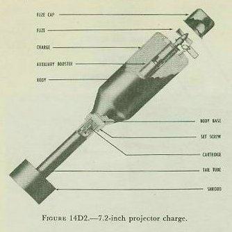
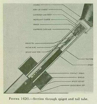
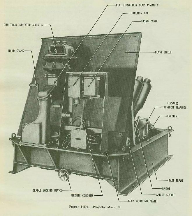
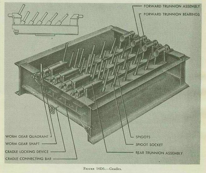
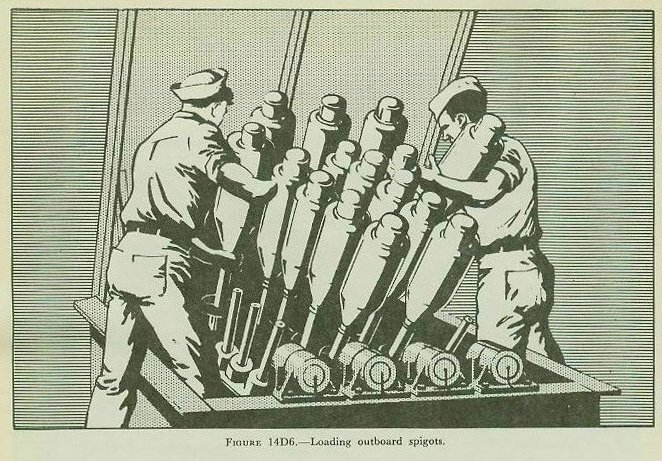
| 14D2. 7.2-inch projector charge The projector charge is similar in shape to the 7.2-inch rocket. It has a head 7.2 inches in diameter, with a tail, fins, and a shroud. (See fig. 14D2.) However, this missile is not a rocket; the propelling charge is an impulse charge of smokeless powder. The fuze arms during flight and is designed to function upon impact only. The explosive charge consists of 30 pounds of TNT. The tail is a steel tube, the forward end of which contains a cartridge case with the propelling charge of smokeless powder. The propelling charge is fired electrically by means of a primer in the base of the cartridge case. As the missile leaves the projector, the cartridge case base falls to the deck. 14D3. The 7.2-inch projector Mkl0 and Mk 11 Several different projectors are used with the 7.2- inch charge. In principle, all of them resemble the Mark 10 (fig. 14D4), which projects a pattern of 24 charges ahead of the attacking vessel. The missiles are loaded on cylindrical bars called spigots, attached to cradles which can be swung about a fore-and-aft axis by means of a roll-correction gear assembly mounted on a gun-train indicator pedestal. This movement is limited, but it allows the spigots to train enough to compensate for roll of the ship and to aid in leading the target. The spigots are so positioned that, when fired, the charges describe an elliptical pattern of about 140 by 120 feet. The base frame of the projector consists of two 18-inch channel beams running fore and aft and two 12-inch I-beams athwartship, forming a box. Each I-beam carries four bearings which support the cradle assemblies. The four 10-inch cradle beams (fig. 14D5) ride on trunnion assemblies welded at each end. The trunnions fit into the bearings on the base frame. The cradles can be tilted on their trunnions about an axis parallel to the keel of the ship. A connecting bar tilts all four cradles simultaneously when the roll-correction gear is operated. Six spigot sockets are welded to each cradle and hold the spigots on which the charges are loaded for firing. The wires of the firing circuit pass through holes in the spigot, as shown in figure 14D3. The ungrounded side of the firing circuit terminates in a firing pin, which is contained in the spigot. The grounded return of the firing circuit is through a spring contact which touches the inside of the projector-charge tail tube. 14D4. Operation The projector is loaded by placing the tails of the missiles over the spigots and sliding them down gently. After the missile is all the way down on the spigot, it is rotated 360° to ensure good contact between the firing pin and primer. (See fig. 14D6.) |
| The charges are fired by means of a ripple switch. This switch has 12 contacts and, as the switch rotates, it completes the firing circuit to the missiles by pairs. the interval between contacts is about 0.10 second (0.20 second in some mods). The firing circuits are so wired that the missiles with the highest trajectories are fired first and those with the flattest trajectories last. Thus all the missiles hit the water at approximately the same time. The average range is about 200 yards. Variations in powder temperature have little effect between 30° and 90° Fahrenheit. Figure 14D7 shows the nominal trajectory and sinking time of the 7.2-inch projector charge. The Mark 11 projector is very similar to the Mark 10 described above. |
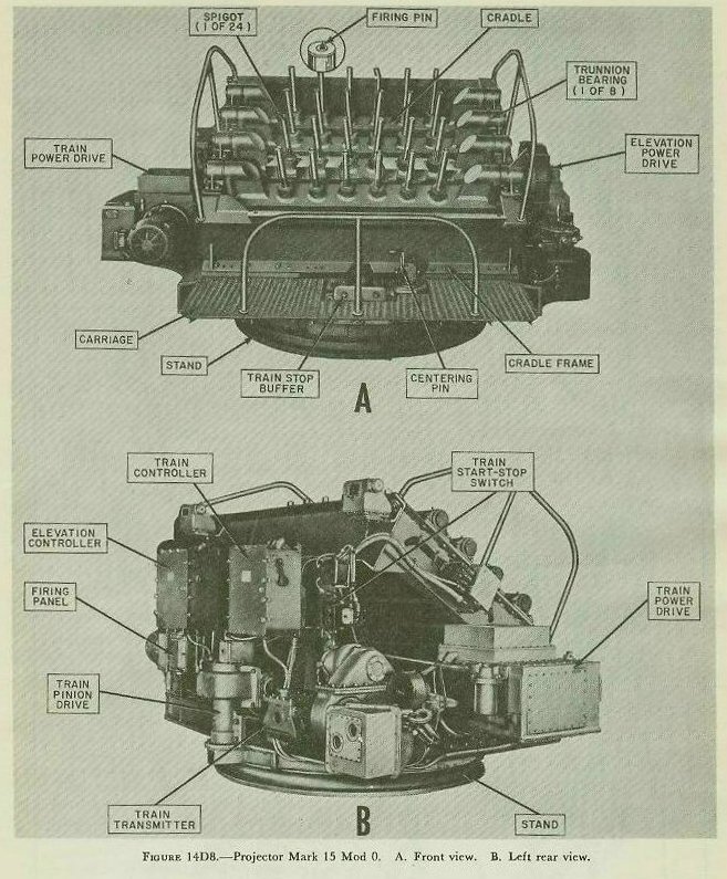
| 14D5. The 7.2-inch Projector Mark 15 In principle of operation and in general external appearance, the A/S 7.2-inch Projector Mark 15 (fig. l4D8) resembles the Mark 10 type described in some detail in the preceding articles. It is equipped with 24 spigots which accept 7.2-inch charges like those already described, and ripple-fires them in a circular pattern. However, the cradles on which the spigots rest are at right angles to the line of fire (the Mark 10’s are parallel to the line of fire), and can rotate in limited arcs of elevation in trunnion bearings. (The Mark 10 projector’s spigots cannot move in elevation at all.) The cradles are cross-connected so that they elevate in unison. The cradles are housed in a trainable carriage mounted on a stand on the deck (as contrasted with Mark 10’s fixed-base frame). The elevating and training parts are positioned by electrohydraulic power drives similar to those used on 40-mm quad mounts. |