| GENE SLOVER'S US NAVY PAGES NAVAL ORDNANCE AND GUNNERY, VOLUME 1 CHAPTER 10 AUTOMATIC CONTROL EQUIPMENT |
| HOME INDEX Chapter 10 Automatic Control Equipment A. Introduction B. Synchros C. Electric-hydraulic systems D. Amplidyne follow-up system E. Other types F. Shipboard tests of automatic control equipment |
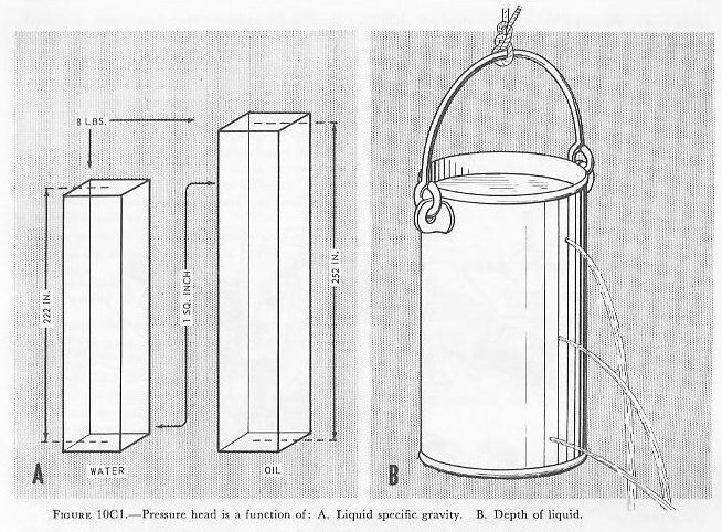
| C. Electric-Hydraulic Systems 10C1. Principles of hydraulic mechanisms Electric-hydraulic power drives are used with all calibers of naval gun mounts from 40-mm mounts to 16-inch turrets. Their great advantage is that they provide positive control at all speeds, and in both acceleration and deceleration, of the most massive moving units-including rotating turret structures weighing millions of pounds. Complete systems are unavoidably complex, especially in the more highly automatic types of installation; but their principles of functioning can be presented relatively simply, once certain elementary facts about the behavior of liquids are known, and once certain basic hydraulic mechanisms are understood. This article presents this fundamental background in simplified, somewhat foreshortened, form. Succeeding articles in this section explain a typical electric-hydraulic system-that for the 5”/38 twin mount. Strictly speaking, hydraulics as a science has to do with the behavior of liquids in motion; hydrostatics has to do with the behavior of liquids at rest. This discussion will not emphasize the distinction. Whether at rest or in motion, all liquids are nearly incompressible, at least within the pressure ranges that are encountered in ordnance hydraulic systems. The liquid in any system is always under the pressure, called pressure head, imposed by its own weight, and this increases in proportion to depth. It varies, of course, with the specific gravity of the liquid. In water, this pressure head is 8 psi at 222 inches below the surface; in a typical oil with a lesser specific gravity, a depth of 252 inches is required to attain this pressure head. Other pressure imposed on an enclosed hydraulic system (for example, pressure imposed by a piston on liquid in a closed cylinder), are distributed equally in all directions throughout the entire volume of the liquid. Thus a pressure imposed at one end of a long liquid-filled tube is communicated undiminished to the other end. (This applies strictly to liquids at rest; other factors modify this behavior when the liquids are in motion.) Although, with regard to pressure transmission, all liquids are about the same, they differ radically in their resistance to flow (otherwise known as viscosity), in their lubricant effect, and in their general suitability for use in hydraulic systems. Hydraulic fluids for ordnance hydraulic systems are petroleum-based oils selected for superior lubricant quality (but they are not lubricants), low viscosity throughout a wide range of temperatures, low volatility, high stability, and compatibility with the metals of which such systems are constructed. Hydraulic systems include some or all of the following main types of components: Pipe or tube lines, to conduct the fluid between components of the systems, and fittings to mate these components. Valves, to direct and control the flow of fluid, and to control fluid pressure. Some valves are hand operated, but most are automatic. Many, like check valves, pressure-regulating valves, and dumping valves, are hydraulically operated; others are operated by electric motors, solenoids, or synchros. Some of the more complex automatic types are described later in this section. Gages, to measure pressure, velocity, and volume of hydraulic fluid. (Ordnance hydraulic systems use mostly pressure gages.) Pumps, to drive the hydraulic fluid through the system. There are many types, ranging from simple rotary and reciprocating units to relatively complex axial-piston pumps whose rate and direction of output can be almost instantly varied from zero to full in either direction without varying their speed of rotation. All pumps in ordnance hydraulic systems are driven by electric motors. Hydraulic motors and work cylinders, whose function it is to convert the energy delivered through the hydraulic fluid to mechanical motion. Most hydraulic motors are actually somewhat modified pumps of one type or another, working in reverse. Pressure chambers, to protect the hydraulic system against sudden shocks and surges, and accumulators, which store a certain amount of fluid under air pressure to equalize fluid flow under sudden heavy demand in excess of the capacity of the pumps, or to complete an operating cycle in case of power failure. Reservoirs and tanks, to store fluid and provide for its expansion with heat. Gaskets to seal joints, and packing to seal openings around moving parts against leakage of fluid. |
 |
 |
 |
 |
 |
 |
 |
 |
 |
 |
 |
 |
 |
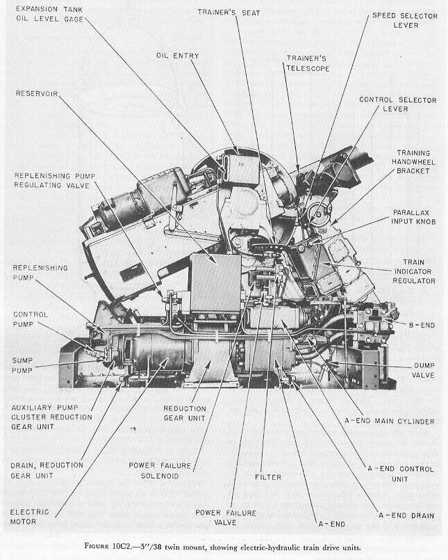
| 10C2. Introduction to 5”/38 twin mount train power drive The system described in this article is a simplified version of the train drive for the 5”/38 twin mount. See figure 10C2. Refinements omitted are needed for smooth operation but do not contribute to an understanding of the principles of the system. The main equipment consists of a variable-speed drive, an indicator-receiver-regulator, and associated auxiliary equipment. |
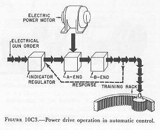
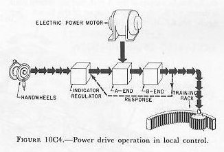
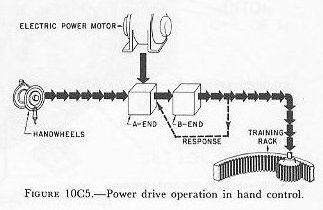
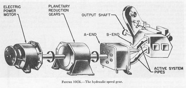
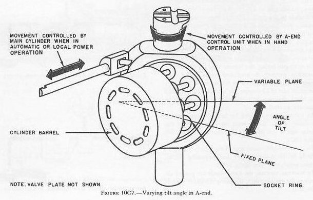
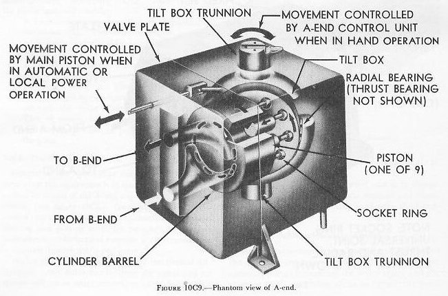
| 10C3. Methods of control This system has four methods of control: AUTO, LOCAL, HAND, and MANUAL. Selection of the type in use is made by the control-selector lever at the trainer’s station. Also located at the station is a speed-selector lever having two positions, HIGH and LOW. It has no function in automatic control, but determines the ratio between handwheel movement and follow-up operation in the other control methods. In AUTO gun laying, the remote signal is received by a synchro receiver, is amplified hydraulically, and causes the training system to follow the signal at a maximum rate of 25 degrees per second. Figure 10C3 is a block diagram representation of this system in automatic control. In LOCAL power control for indicator gun laying, movement of the handwheels takes the place of the remote signal entering the indicator-regulator. See figure 10C4. In HAND control, movement of the handwheels goes directly to the A-end control unit, bypassing the indicator-regulator. See figure 10C5. In MANUAL control, the handwheels are geared directly to the training rack, bypassing the entire power-drive unit. 10C4. Variable-speed drive (hydraulic speed gear) The speed gear consists of a variable-displacement hydraulic pump, the output of which drives a hydraulic motor. The pump is called the A-end, and the hydraulic motor is called the B-end. The hydraulic system through the two units and the two large interconnecting pipes is referred to as the active system. The A-end is driven at constant speed by an electric power motor through a set of planetary reduction gears. The B-end, as already mentioned, is driven by the hydraulic output of the A-end, and the mount itself is driven by the mechanical output of the B-end. See figure 10C6. By controlling the variable output of the A-end, the direction and speed of rotation of the B-end can be controlled; therefore, the direction and speed of the motion of the mount can be controlled. The hydraulic output of the A-end is controlled by varying the angle between the socket ring and cylinder barrel of the rotating group of the A-end. See figures 10C7, 10C8, and 10C9. This angle is called the angle of tilt and is controlled by the A-end control unit when the equipment is in HAND control. In AUTO and LOCAL power control, the angle of tilt is controlled by the position of the main piston. The position of the main piston is in turn controlled by the hydraulic follow-up system. The cylinder barrel rotates in a fixed plane, while the socket ring rotates in a plane whose angle to the fixed plane of rotation of the cylinder barrel may be varied. The angle between these two planes is the angle of tilt. See figures 10C7 and 10C8. |
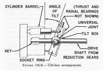
| The socket ring is mounted inside a large, steel, cup-like casting. This yoke is called the tilt box and does not rotate with the socket ring. Therefore, suitable thrust and radial roller bearings are provided to support the socket ring inside the tilt box. The tilt box is trunnion-mounted in large ball bearings so that the tilt box and the socket ring may be tilted anywhere within a limit of ±20 degrees from the zero tilt position. A universal joint is provided so that the socket ring may be rotated by the drive shaft as the angle of tilt varies between its limits of ±20 degrees. The same drive shaft that rotates the socket ring rotates the cylinder barrel. The cylinder barrel is keyed to the drive shaft. See figure 10C8. |
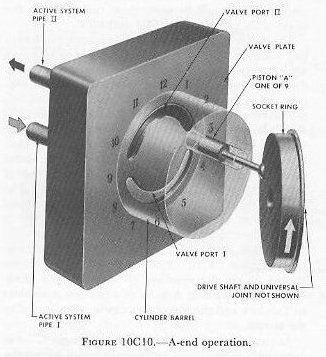
| To follow piston A through a complete revolution, refer to figure 10C10. Note that the numbers are arranged as are the numbers on the dial of a clock. Then consider piston A to be at a position equivalent to 3 o’clock and the rotation clockwise as indicated by the arrows. As rotation progresses, piston A will begin to move outward in relation to the cylinder in which it operates. The relative motion of the piston is outward until the piston is at the 9 o’clock piston. The piston motion up to this point has been such as to draw oil into the cylinder in which the piston operates. The oil has entered the cylinder through valve port I and active system pipe I. Continuing the rotation from 9 o’clock to 3 o’clock it must be noted that the relative motion of the piston in its cylinder is now reversed and is inward, forcing oil out of the cylinder through valve port II and active-system pipe II. |
| At 9 o’clock and at 3 o’clock, where the relative motion of the piston in its cylinder reverses and where the relative motion is zero, lands are provided in the valve plate to separate port I from port II. These two points are points of commutation where the piston motion reverses from that of drawing in oil to that of pumping out oil under pressure. The two lands separate the high-pressure discharge port from the low-pressure intake port. . The width of these lands must be at least as great as the diameter of the opening at the end of the cylinder. This is necessary in order to prevent a hydraulic short circuit between the low-pressure port and the high-pressure port as any one of the nine pistons of the rotating group passes over one of the lands. The cylinder barrels bears against the valve plate at all times, and the construction of the two parts is such that leakage is reduced to a minimum. The tilt-box trunnions are adjacent to the points designated as 6 o’clock and 12 o’clock. See figure 10C9. The tilt box rotates within limits about an axis through these two points. It should be evident at this point that, with the tilt shown, the pumping action is such as to force oil out through port II and to draw oil in through port I. That is, the oil drawn in through port I at low pressure is pumped out through port II at high pressure. It should also be noted that if the angle of tilt is reversed the direction of flow is reversed, and that the volumetric rate of pumping depends upon the value of the angle of tilt. |
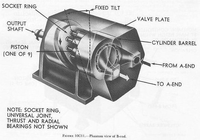
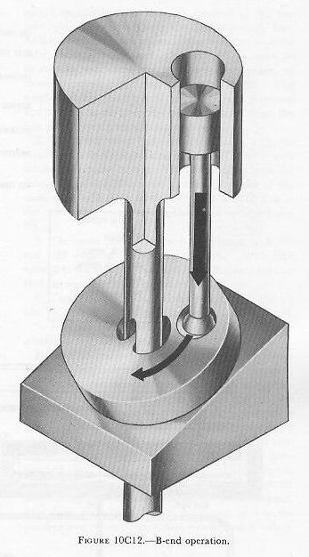
| The active-system piping leading from the two valve-plate ports of the A-end provides for flow of oil through to the B-end. The B-end is similar in construction to the A-end, except that the tilt of the socket ring is fixed. The angle of tilt of the B-end is built into the unit and cannot be changed. See figure 10C11. The flow of oil under pressure to the B-end will exert forces normal (at right angles) to the faces of the pistons open to the valve port receiving the oil under pressure. See figure 10C12. These forces on the piston faces will result in: 1. A thrust component along the axis of rotation of the socket ring. This component does no useful work and is neutralized by a suitable thrust roller bearing. 2. A turning component which will rotate the socket ring. This force component is at right angles to that described in 1. The cylinder barrel will rotate, driven by the rotation of the socket ring, through the drive shaft and universal joint. This, of course, will cause the B-end to rotate, and thereby provide the power required to drive the guns. 10C5. The A-end control unit Control of the speed-gear output for driving the guns when the equipment is in HAND control is accomplished by action of the A-end control unit. In HAND control (see figure 10C5), the signal to the A-end control unit is transmitted mechanically through shafting and gearing from the pointer’s or trainer’s handwheels. Mechanical response is also transmitted to this unit through shafts and gears. Within the unit is a special type of mechanical differential. Any difference between the signal and response will cause axial movement of a shaft which introduces a change in the value of the angle of tilt of the A-end tilt box. The action of the A-end control unit is to change the angle of tilt until mechanical response and therefore gun movement is synchronized with the hand-wheel motion. |
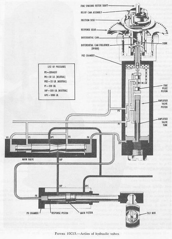
| 10C6. The indicator-receiver-regulator The indicator-receiver-regulator (commonly called the indicator-regulator) contains all the equipment necessary for (1) receiving the order signal and the response, (2) comparing them to obtain the error signal, (3) amplifying the error signal, and (4) transmitting it to the A-end properly. It is equipped with dials which indicate the order signal and the response. The indicator-regulator is in use only when AUTO or LOCAL power gun laying is employed. (See figures 10C3 and 10C4.) Figure 10C13 shows only the major parts of the (train) indicator-regulator. It demonstrates the control of the principal valves by movement of the fine synchro receiver. Rotation of the synchro rotor causes the fine pilot piston to move up or down. The amplifier valve piston follows the movement of the fine pilot piston. This positions the main valve, and the main valve controls the main piston, which is attached to the A-end tilt box. As the B-end drives the mount, response gearing rotates the response gear, which repositions the fine pilot piston to bring the system to rest. In automatic control, the synchro receiver rotor receives a gun-train order from the synchro transmitter in the computer. As the rotor moves, it turns the rotating fork through the relief-cam assembly. The ends of the fork fit in slots in the differential-cam follower (spider). Since the spider is constrained to move in helical grooves in the differential cam as it is rotated, it moves up or down. Attached to the lower end of the spider is the fine pilot piston which moves with it. Now, as the mount moves in train as a result of the above signal, gearing from the B-end output shaft turns the response gear of the differential cam. The helical grooves of the differential cam are moved while the rotating fork is preventing the spider from rotating. Thus, the spider and the fine pilot piston are raised or lowered in accordance with the signal. On figure 10C13, we will trace one cycle of operation of the hydraulic valves shown. Assume that a signal has caused the fine piston to move up: 1. Oil in chamber PR2 (at the top of the amplifier valve) escapes through the port (opened by the fine pilot piston movement) to the PX (exhaust) line. As the pressures on the top and bottom of the amplifier valve piston are no longer in balance, PR pressure on its bottom will cause the amplifier valve piston to move up, closing the port from PR2 to PX. The amplifier valve piston moves exactly the same direction and amount as the fine pilot piston, and it follows the fine pilot piston almost instantaneously. 2. The main valve had been in balance, with the pressures P1 and PX working against PR. Now with the loss of volume from the PR side resulting from the rising of the amplifier valve piston, the piston of the main valve will move to the right. The IHP line to the center of the main valve is then open to the exhaust Px. 3. The main piston had been in balance, with PR and IHP working against pressure HPC. With IHP opened to the exhaust, the resulting unbalance permits HPC to force the main piston to the left. 4. The main piston is directly connected to the tilt box, so that its movement produces an angle of tilt. 5. Now the B-end drives the mount until response gearing brings the system to rest. It must be realized that the preceding paragraphs deal with the problem in the simplest terms. Actually, two synchro receivers are used to initiate the movement of the pilot piston. One is a coarse synchro; the other a fine at the ratio of 1:36. If the signal differs from the existing position of the mount by an angle equal to 3.8 degrees, the coarse synchro will take control to move the fine pilot piston to its maximum position and keep it there until this difference becomes less than 3.8 degrees. Then the fine synchro, through the cam, will again perform its function as described above. Also there are other valves in the system such as the acceleration, offset control, and synchronizing valves. |